


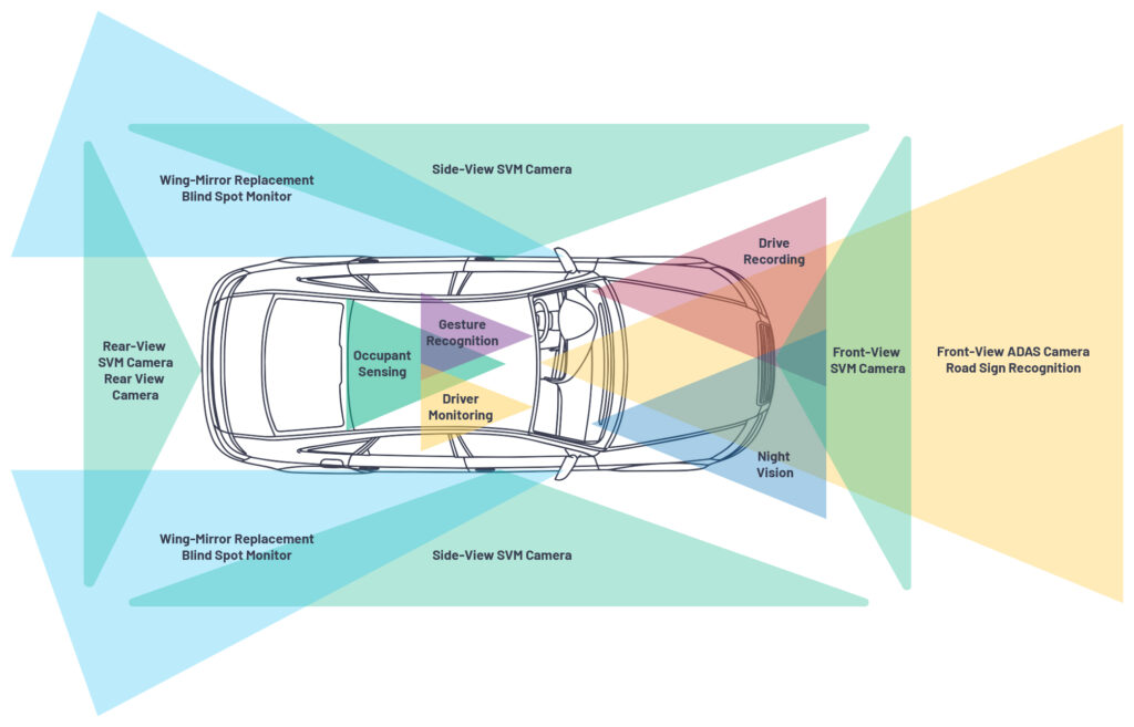
Camera systems and camera link technologies are being deployed in an ever-increasing range of applications in vehicles to assist drivers and augment the driving experience. Traditional rear-view camera (RVC) systems featuring a single camera are being superseded by surround-view systems (SVS) featuring four or more cameras that provide a 360° perspective of the vehicle. Drive recorders, blind spot monitoring, night vision, road sign recognition, lane departure monitors, adaptive cruise control, emergency braking, and low speed collision avoidance systems all help ease the load on the driver. To augment the driving experience, cameras are also being introduced for applications as diverse as driver vital sign monitoring, occupant detection, and gesture recognition for human machine interfacing (HMI). Developments in camera systems are even allowing automotive manufacturers to reimagine the vehicle silhouette through the replacement of traditional features like wing mirrors.
Many of the diverse array of camera applications listed share a genesis in the standard definition (SD) RVC systems still featured in many of today’s vehicles. SD camera systems have been routinely deployed in automotive applications for well over a decade, proliferating from premium vehicles into the broader vehicle line in response to legislative requirements and customer expectations. SD video solutions offered automotive OEMs many valuable benefits: low risk due to the maturity of a technology proven out in the consumer television industry over many years, low bandwidth demands resulting in the ability to use cheap cables and connectors while also maintaining controlled emissions, and a mature range of video encoders and decoders with proven handling for potentially unstable video inputs.
Today, the ubiquity of ultrahigh definition (UHD) displays in consumer devices is driving the requirement for larger and higher definition displays in all types of vehicles. While an SD video solution may appear satisfactory on a smaller display, today’s consumers can easily perceive its shortcomings on a larger display (for example, the lack of high frequency detail caused by the limited bandwidth of SD video or cross-color artifacts introduced when separating the luminance and chrominance signals from one another in the modulated signal). The trend toward larger displays has resulted in automotive OEMs being challenged to upgrade the rest of their camera architectures to high definition. One key building block involved in addressing this challenge is the camera link technology selected to transfer image data from the camera to the receiving unit (for example, ECU or display).
The first use case characteristic when selecting a new camera link technology for an application is the bandwidth required. Camera systems range widely in terms of bandwidth requirements. Traditional RVC systems using SD video resolutions require low bandwidths (for example, 6 MHz). SVM systems, typically employed at low speeds, use low refresh rates (for example, 30 Hz) to maximize exposure, which can limit the bandwidth required. Wing-mirror replacement systems, which operate across the whole range of a vehicle’s operating speeds, use higher refresh rates (for example, 60 Hz or higher) to minimize latency, which demands increased bandwidth. Front facing cameras for autonomous driving applications demand ultrahigh resolutions (for example, 18+ MPixel) and hence have very high bandwidth requirements. Many camera link technologies exist to deliver a broad gamut of bandwidth capabilities—their selection is influenced by, and can influence, several aspects of the camera system and overall vehicle.
Image Quality
The image quality that a camera link technology enables is a critical factor in the architecture design. Sending video data across a camera link technology that does not provide sufficient bandwidth could result in the loss of image integrity or complete image loss. Image degradation caused by the camera link technology can be assessed by measuring factors such as image sharpness and dynamic range.
Cable Attributes
The complete cable assembly or wiring harness of a modern vehicle is one of its most complex, heavy, and difficult to install components. With the average car featuring well over a kilometer of wiring, the harness demands serious considerations. To a first order, applications with higher bandwidth requirements (for example, ultrahigh resolution front facing cameras for autonomous vehicles) require high quality, heavy cables. Cable weight has emerged as a topic of increased scrutiny in recent years given the focus on making cars lighter and more efficient in an effort to increase range for combustion engine vehicles and electric vehicles alike. For applications involving complex routing through a vehicle, the bend radius supported by a cable may be important. For applications where the camera is located in a hinged body part (for example, the door for SVM systems or trunk lid for RVC and SVM systems), the robustness of the cable to open and close cycles is critical. For applications where the cable may be exposed to harsh environments, water resistance may be required.
Regardless of the camera link technology and cable type selected, every centimeter of cable has a cost and, when all of the costs of the harness are collated, it can result in the harness being one of the three most expensive elements of the vehicle.
Traditional SD video solutions, due to their low bandwidth demands, facilitate the use of extremely cost-effective, light cables. In many instances, unshielded twisted pair (UTP) cables, similar to those normally used for low speed control links such as CAN, are used for SD video solutions.
Connectors
Another crucial element of the wiring harness and its connected modules are the electrical connectors. In addition to connecting the harness to control modules, sensors, or motors, the connectors are also used to join different sections of the same cable within the harness (in-line connectors). In-line connectors are used extensively within the automotive industry to simplify the construction, installation, and serviceability of the harness. For example, using an in-line connector very close to a camera means that, if the camera is damaged, it can be replaced without significant disturbance to the rest of the vehicle’s wiring harness.
Connector selection, in common with the cable selection described above, can be a significant determinate of the overall cost of a camera system. High resolution systems typically demand connectors that support higher bandwidths and are therefore more expensive.
Other connector considerations include the connector’s footprint on the PCB and ECU surface, whether the connector must be sealed or unsealed, and if color coding/keying is required.
Traditional SD video solutions facilitate the use of cost-effective connector solutions on both the camera and ECU or head unit (HU). For example, the video signals of an SD video RVC system are often routed into the ECU or HU with other signals (for example, control networks and the required power supply signals) on a multipin connector; a digital link typically requires dedicated connectors, which introduce PCB and packaging constraints on an ECU.
Vehicle Architecture
The architecture of the vehicle involved can have several influences on the selection of suitable camera link technology. Cable lengths in standard vehicles can frequently range up to several meters in length and, with consumers trending toward larger, sports utility vehicles, cable lengths are increasing. Some vehicle architectures have additional features that can pose new cable length challenges, such as trailer reverse assistance to support the reversing and maneuvering of trailers. Commercial vehicles are another architecture challenge in which camera systems stretch cables to their maximum length. Most camera link technologies can support any of these vehicle architectures and features, but some may demand additional modules such as repeaters or retransmitters to support long cable lengths.
EMC
The electromagnetic emissions and immunity robustness of a cable solution is another critical factor in the camera link technology selection process as the cable can become an antenna within the vehicle with detrimental results. The proliferation of electrical and electronic systems in the vehicle has resulted in an increasing dependence on such systems existing together in a compatible fashion. It is not acceptable for one system (for example, an RVC system) to influence, or to be influenced by, another system (for example, an electric vehicle traction motor or electric seat mechanism), when either is enabled. To this end, it is critical that link technology solutions are considered for their emissions and immunity performance prior to selection.
To ensure internal or external aggressors do not interfere with systems in the vehicle, automotive manufacturers will test all systems to their specific EMC standards. These tests are first done at a system level (for example, a rear-view camera or surround-view system). This testing is expensive, time consuming, and challenging, but ensures that each module has a high level of robustness before being integrated into the vehicle. Once the system-level testing has been successfully completed, the automotive manufacturer must also verify the system operation and performance in the vehicle by testing the system’s ability to operate when being bombarded by high power radiated signals (radiated immunity). The manufacturer will also measure the receiving bands of all antennae in the vehicle (for example, FM, GPS, cellular, Wi-Fi, etc.) to ensure no interferer signals are present. Resolving EMC issues at the vehicle level can be expensive and time consuming.
Other Requirements
In addition to the requirements already outlined, a myriad of other demands guide the selection of a camera link technology, such as control channel availability, pixel accuracy, and ASIL ratings.
Summary
The selection of a camera link technology when designing a camera system is influenced by a multitude of factors. The selection of a camera link technology also influences several aspects of the vehicle into which it is integrated. Traditional RVC systems, built on SD video technologies, offered automotive OEMs an extremely reliable and cost-effective method for transferring video within the vehicle. In recent years, however, consumer trends have emerged to render SD video systems less and less acceptable on larger displays. Legislative developments and consumer expectations have also combined to continue increasing the number of cameras in each new vehicle.
These trends and developments serve as a backdrop to the emergence of several camera link technologies that are used in today’s vehicles across the spectrum of automotive camera systems. Camera link technologies today still range from the SD video technologies (for example, CVBS) proven in traditional SD RVC systems, through high definition analog link technologies, to high definition digital link technologies.

SD video technologies can only enable low bandwidth applications but conversely require very cost-efficient cables and connectors. Digital link technologies enable high bandwidth applications and offer benefits such as pixel accuracy, but typically require more expensive cables and connectors. High definition analog link technologies offer a compromise between the two aforementioned solutions—delivering high definition video over cost-effective cables and connectors.
C2B™ is one such high definition analog link technology that delivers automotive OEMs and tier 1 suppliers an attractive blend of support for EMC compliant high definition video using cost-effective cables and connectors.
C2B Automotive Camera Link Technology
C2B is a high definition analog video transmission technology brought to the market by Analog Devices.
Designed from the outset as an automotive camera link technology, C2B supports the transfer of HD video from transmitter to receiver at resolutions of up to 2 MPixel (1920 × 1080). C2B is designed to utilize the maximum bandwidth capacity of the UTP cables and connectors traditionally employed for SD video systems. The innovative equalizer architecture of C2B allows for the support of cable lengths up to 30 m without retransmission. To ensure that C2B meets all automotive requirements, it features several optimizations for EMC (optimized signal construction, antialias filters, spectrum shaping filters) and benefits from Analog Devices’ trusted reputation as an automotive supplier.
C2B features a control channel that can handle the transmission of I 2 C signals at up to 400 kHz, up to four GPIO signals, and interrupt signals from the camera module. This facilitates system architectures including not only the local configuration (a microcontroller unit (MCU) in the camera module and an MCU in the ECU/HU) but also the remote configuration (an MCU in the ECU/HU configuring the camera module). The four GPIOs are used for transferring static signals across the C2B link. Two interrupt signals are provided to allow the C2B transmitter communicate status information to the C2B receiver. C2B applies CRC checking to the control channel data and can automatically initiate retransmission should an issue occur.
C2B supports value adding features for automotive customers such as cable diagnostics (information gathering on the occurrence of cable short to battery and short-to-ground events) and frame count collection, generation, decoding, and transmission to provide insight into the integrity of the transmitted data.
Defined and designed for automotive applications, C2B employs several blocks to ensure EMC compliance over low cost UTP cables and low cost unshielded connectors. These include echo cancellation for impedance mismatch, broadband common-mode rejection (important when using UTP cables) and spectrum shaping of the output signal to provide reduced emissions. C2B is tested and compliant to international device-level EMC standards and international systemlevel EMC standards (CISPR 25 class 5 [emissions], ISO 11452-2/ISO 11452-4/ISO 11452-9, ISO 7637-3 [immunity], ISO 10605 [ESD]).


These features make C2B an attractive solution for two types of automotive manufacturer: those who are still using SD camera solutions and are seeking a low risk upgrade path, and those who have already switched to digital link technology-based camera solutions and are seeking a cost reduction path from a high definition analog link technology.
Application spaces in which C2B offers significant system cost advantages over alternative technologies include rear-view cameras, surround-view camera systems, e-mirror, and occupant monitoring systems. The independently validated visually lossless nature of C2B can provide a similar high definition performance to digital link technologies while delivering significant system-level cost savings.
Conclusion
C2B offers automotive manufacturers a compelling link technology solution that can be used to facilitate the upgrade of an existing SD camera solution to HD or to facilitate the migration of a system using a digital link technology to reduce system cost. Information on C2B technology and the products available for automotive applications can be found at analog.com/c2b or by contacting your local Analog Devices sales office. Evaluation boards for the C2B transmitter (ADV7992) and C2B receiver (ADV7382/ADV7383) are available from Analog Devices to accelerate technology investigation and system prototyping. During system prototyping, the C2B transmitter evaluation board can be used as a C2B source if developing a receiver, while the C2B receiver evaluation board can be used as a C2B sink if developing a camera.


 combined with superior switching performance")


