Abstract
This article discusses how to implement a hardware agnostic driver in a project. A plug and play approach can benefit embedded software or firmware designers of any experience level. To review the basic functions implemented in the driver along with the software structure of an embedded system, see the article, “Leveraging a Hardware Agnostic Approach to Ease Embedded Systems Design: The Basics.”
Introduction
Designers working with embedded systems are often tasked with programming the driver, and therefore the firmware, to ensure that selected sensors realize their desired basic functions. This is quite time consuming. One solution to this combines hardware with software and firmware to enable a plug and play approach to sensor selection and system integration. In addition to making sensor integration easier, a hardware agnostic driver provides the benefit of a ready-to-use solution that can be applied to future designs. This article will use an inertial measurement unit (IMU) sensor as an example, but the approach is scalable to other sensors and components. The driver is configured using the C programming language and tested with a generic microcontroller.
Driver Implementation
All the pictures referred are in the appendix, where the reader can find the code.
- adis16500_rd_error_flag
The implementation of this function is available in Figure 10 in the appendix. It reads the error flags contained in the ADIS16500_REG_DIAG_STAT register that if no error is occurring, has all the bits at 0. The possible errors are 10, so the function will return a structure called ADIS16500_ERROR_FLAGS containing 10 Boolean fields, one representing each error. The function simply reads the ADIS16500_REG_DIAG_STAT register and checks its bits with particular error masks, and whenever a logical 1 is found, the particular field of the structure will be set to true.
- adis16500_rd_temp
The temperature reading function follows the same approach implemented in the case of acceleration and gyroscope (detailed in the first article in this series). The read value will be expressed in °C. The binary value is contained in a 16-bit register, the ADIS16500_REG_TEMP_OUT. After that there will be the binary to twocomplement conversion. Once the two-complement value is obtained, it will be multiplied by the temperature scale factor, which is expressed in °C/LSB, giving the final value in °C ready to be registered in the pointer passed as input. The function implementation is available at Figure 9 in the appendix.
- adis16500_get_ts_usec
This function is used to get the timestamp of the IMU in μs. The approach is exactly the same as for adis16500_rd_temp function. The implementation is shown in Figure 9 in the appendix.
- adis16500_rd_data_cntr
This procedure reads the number of data that has been output. This is done by simply reading a register called ADIS16500_REG_DATA_CNTR. When the register reaches the maximum value, it will restart from 0. How the function has been implemented is shown in Figure 9 in the appendix.
- adis16500_wr_acc_calib
This is the function to be invoked if the designer wants to do a custom offset calibration. In that way an offset can be added to the value read from the output data registers so that the x, y, z calibration values will be added to x, y, z acceleration data. The input of the function is a pointer to an ADIS16500_XL_OUT type structure. The latter structure contains x, y, and z float type fields. The goal of the function here is to pass from float to two-complement value and then from two-complement to binary value. All the steps are shown in Figure 11 in the appendix. At this point the binary value needs to be written in the bias registers, so, for example, for x-axis there are two registers to be written: ADIS16500_REG_X_ACCEL_BIAS_L for the less significant 16 bits, and ADIS16500_REG_X_ACCEL_BIAS_H for the most significant 16 bits. The same is true for the y-axis and z-axis, according to their respective bias registers. In order to check if this procedure is doing the right things, the IMU sensor was placed with z-axis pointing to the sky in a perpendicular way. In that condition the acceleration values are almost 0 for x-axis and y-axis and almost –9.81 m/s2 (–g) for the z-axis. By invoking the calibration function passing to it a calibration structure with x, y, and z fields all equal to –9.81 m/s2 what is read is x = –9.81; y = –9.81; z = 0, so the calibration offset function is working.
- adis16500_wr_gyro_calib
The offset calibration function regarding the gyroscope follows exactly the same procedure of the acceleration one. Of course, it is done in accordance with the data sheet with gyroscope bias registers.
The article is focused on the IMU sensor driver, but the software/firmware structure will be the same for each type of sensor. Therefore, to generalize the implementation to all sensors it can be said that the only difference is the communication protocol (SPI, I2C, UART, etc.) that links the microcontroller to the sensor. The way in which the sensor is initialized is still valid, as the initialization phase records the functions of transmitting and receiving through the communication protocol.
How to Include and Use the Driver in a Project
Apart from the simple directives about hardware connections between the sensor and the microcontroller unit (MCU), there are also guides on how to include the driver from a software and firmware point of view.
There is no one-size-fits-all approach to organizing sensor drivers. The proposed approach is shown in Figure 1. There is a folder called userlib that contains all the sensor drivers. In this example, there are only IMU sensor drivers, but the procedure would be similar if the project included more sensors. Inside userlib there are two folders, include and src. The include folder contains the header file of the driver, in our example will be adis16500.h, while into src there is the source file, or adis16500.c. Inside userlib there is also a makefile, which specifies the include directives, as can be seen in Figure 2.


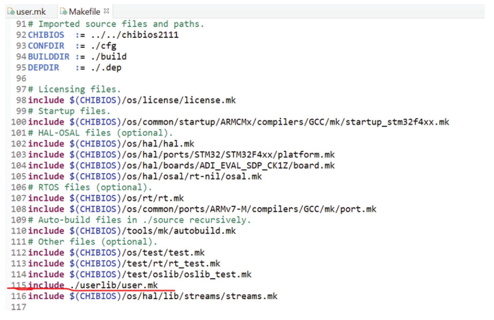
Figure 3 shows the principal makefile. It is located at the application layer, near main.c. This makefile includes user.mk as it has been shown in the red-underlined line of Figure 3 (line 115 of the code).

Thanks to the makefile (.mk) the designer can include the driver’s interface at the application layer, inside the main.c for example, and can invoke all the public functions of the sensor’s driver. In that way there will be a link between application layer and sensor driver layer. The application layer is the one who knows the sensor’s driver interface (adis16500.h). For that reason the link between sensor driver layer and peripheral drivers layer will take place at the application layer through the already discussed initialization procedure. In the IMU sensor specific case the transmitter, receiver SPI function and the system delay function will be defined in the main.c file, as in Figure 2 in the appendix. Here the three functions are exactly following the prototypes in the driver’s header file, or the ones shown on the top of Figure 3 in the appendix. Inside these three functions are the functions offered by the peripheral driver layer, as spiSelect, spiSend, spiReceive, spiUnselect, and chThdSleepMicroseconds. For those reasons, the SPI receiver, transmitter, and system delay functions represent the link between peripheral drivers layer and sensor driver layer, which are the functions that will be assigned to the initialization structure, as in Figure 2 in the appendix. This is all that is needed to include the driver in a project.
To get outputs from the sensor, the designer can use the functions explained in the adis16500_rd_acc and adis16500_rd_gyro sections. There is no one-size-fits-all approach to reading the sensor, but an example is provided in Figure 4.

In this example, there is an infinite loop in the main.c where a Boolean static variable called _adis16500_data_ready is always checked. This variable is related to a callback function, and it will toggle to TRUE where the DR pin goes high, which means that new data is ready. Under that condition the main function will invoke the adis16500_rd_acc and adis16500_rd_gyro functions. By running the IMU sensor at full speed, the designer will be able to acquire data with an output data rate (ODR) equal to 2 kHz.
Conclusion
This article illustrates driver functionalities and a hardware agnostic approach that makes sensor integration easier. A hardware agnostic driver provides the benefit of a ready-to-use solution that can be applied to future designs.


