Many applications need to switch circuits with high isolation, or require the ability to switch high voltages and high currents with a low power control signal. Sometimes, a solution based on semiconductors isn’t adequate. In these instances, designers need to choose between electromechanical relays and contactors and understand how to apply them correctly.
Electromechanical relays can switch relatively high currents using just a few volts of control signal, and they provide good voltage isolation between the control signal and the switched power. However, really heavy current loads and very high switching voltages call for contactors, which are electromechanical relays on steroids. Most design engineers are familiar with the many types of relays available ranging from reed relays to heavy duty ones. Few outside of the industrial power industry are aware of contactors, which have broad use when switching high voltage circuits and very high loads.
This article will discuss the difference between relays and contactors and the applications to which each are best suited. It will introduce a variety of relay and contactor solutions, and will provide practical design tips for using each type.
Relays versus contactors
Both relays and contactors are electromechanical devices that use an electromagnetic solenoid to actuate one or more pairs of contacts. A single pole relay or contactor has a single pair of contacts. There are also double pole relays and contactors and the number of contacts can get quite large. Contacts may be normally open or normally closed. Some relays and contactors also have double throw contacts that combine a normally open and normally closed contact.
Relays are fine for switching low and medium current loads at relatively low voltages, and they’re available in many form factors including plug-in and board mount versions designed to be soldered onto a PCB. Contactors are designed for high current and high voltage loads.
The type of relay or contactor chosen depends heavily on the type of load being switched. Here is a summary of different types of loads along with tips to deal with these loads:
- Resistive loads exhibit no current surge when power is first applied. The most common example of a resistive load is a simple heater. If its specified current draw is 10 amps, it can be switched safely with a 10 amp relay. There are very few purely resistive loads in the real world. Most loads present a combination of two or more load types.
- Lamp loads draw high currents when power is first applied. An incandescent bulb filament has a high temperature coefficient. When it is cold, the filament resistance often can be a mere 5 percent of the resistance of a hot lamp, thus drawing 20 times more current when cold compared to after the lamp has heated. A 75 watt incandescent light bulb draws a little more than half an amp during normal operation, but when first turned on, the cold filament draws an inrush current of 13 amps. Although this current surge only lasts about a tenth of a second, any relay contacts driving an incandescent lamp load must account for the high inrush current.
- Motor loads also draw high currents when power is first applied. A single phase, 110 volt AC, 1/3 horsepower synchronous motor normally draws just over 4 amps. At start up or with a locked rotor, the same motor can draw more than 24 amps. If the mechanical load is released from the motor and it runs unloaded, the motor can draw 6 amps.
- Capacitive loads exhibit high current surges at power up because a capacitor tries to maintain a constant voltage across itself. Switching a voltage to an uncharged capacitor is like momentarily driving a short circuit. This sort of high current at power up can weld relay contacts shut. Typical capacitive loads include DC power supply outputs and other filtered power sources.
- Inductive loads have a soft turn on as the load current rises slowly when power is applied. However, there will be an inductive voltage spike induced across the relay’s contacts when the load is switched off because an inductor tries to maintain a constant current through itself. The induced voltage spike can be large enough to cause an arc across the relay’s contacts, which degrades the contacts by melting and pitting the contact surface every time the power cycles. That explains why some relays have integrated snubber diodes across their coils, to prevent arcing. Types of high inductance loads include solenoid actuators, electrically operated valves, and relays.
Relays in detail
Important relay specifications include coil voltage and AC or DC coil operation, contact current rating and configuration (normally open, normally closed, multiple pole), the number of contacts, and the actuation/release times. It is important to avoid switching currents that are too small for a relay to operate reliably. Proper operation of a relay’s contacts relies somewhat on the switching of some specified minimum current, often referred to as the wiping current because it burns off trace contaminants that may build up on the relay’s contacts.
A relay’s lower limit for the current that can be reliably switched depends on several factors such as contact material, contact geometry, and mechanical sliding of the contact surfaces. All of these factor into a relay’s minimum switching current specification. Relays with gold plated contacts and those with bifurcated (split) contacts can reliably switch currents as low as 10 milliamps.
Reed and mercury wetted reed relays are suited to low level switching applications. For example, TE Connectivity Potter and Brumfield Relays’ JWD and JWS reed relays are available with a range of coil voltages ranging from 5 to 24 volts DC and in a variety of single and double pole configurations.
For instance, TE Connectivity’s JWD-171-10 reed relay has a 24 volt coil with an integral snubber diode, and one normally open contact rated for switching a maximum 500 milliamp current at 20 volts. The JWD series of reed relays is designed to be mounted on a circuit board and has the same footprint as a 14 pin DIP integrated circuit, although they only have eight pins (Figure 1).
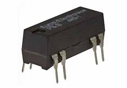
Reed relays are not usually rated for switching higher loads, which require a physically larger package to accommodate larger high current contacts. For example, Omron Electronic Components’ G2R-1-DC24 general purpose relay is rated to switch 10 amps at 24 volts. It has a 24 volt DC coil and a single pole, double throw contact arrangement. This relay is somewhat larger than TE Connectivity’s JWD series reed relay, but this relay is still designed to be mounted on a printed circuit board (Figure 2).
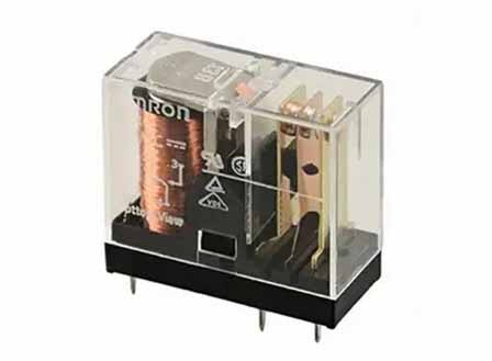
Omron also offers a similar relay, the G2R-1-SND-DC24(S), which is designed for socketable plug-in applications. There are several matching companion sockets for this relay style in versions compatible with DIN rail, panel mount, and through-hole circuit board mounting.
Contactors in depth
A contactor is the heavy duty industrial equivalent of a relay and is a standard component in factory and industrial applications. Contactors are somewhat more rugged than relays and are usually designed to easily mount on a standard DIN rail. Some have additional mounting holes allowing them to be directly bolted to a flat surface. They’re designed to switch high loads such as fractional and multiple horsepower, multiphase motors; large heating loads, and industrial/commercial lighting. Consequently, contactors are designed to accept large, high current wires.
Like relay coils, contactor coils are available with AC or DC specifications. Contactors designed to be driven by a PLC (programmable logic controller) usually have 24 volt DC solenoid coils, but coil drive ratings for AC line voltages (including 110, 220, 240 volts AC) are also common.
As with relays, a contactor’s electromagnetic solenoid coil magnetically attracts an actuator or plunger that physically makes a connection between one or more pairs of the contactor’s heavy duty electrical contacts. Unlike relays, contactors are assembled in a modular fashion, making it easy to change out the solenoid coil to change voltage. Relays are generally not constructed in a modular fashion and changing a relay’s configuration generally requires replacing the entire relay. Contactors’ modular construction also allows users to modify the array of actuated contacts.
Contactors usually have multiple sets of contacts. Sometimes a contactor will only incorporate high current contacts, but the contactors can have a mix of high and low current contacts used for simultaneous switching of power and signal circuits, respectively. The low current contact is also called an auxiliary contact. The difference between the two contact types is that high current contacts are physically larger than the low current contacts to carry the higher load current. A contactor designed to drive a three phase motor might have three high current contacts to carry the motor power, and one auxiliary contact to signal the motor’s actuation state.
For example, Omron Automation & Safety’s J7KNA-AR-31 24VS contactor has a 24 volt DC solenoid coil and a four pole, single throw contact arrangement (Figure 3). The contacts are rated at 10 amps with a maximum switching voltage of 600 volts AC. Omron’s J7KNA-AR series is modular and many options can be specified including the coil voltage, contact arrangement (with 4, 6, and 8 pole versions available), and mounting method.
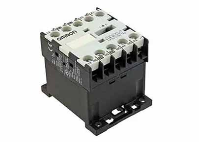
Mechanically, contactors have evolved over time so that it’s now possible to gang contactors together mechanically to provide for multiple simultaneous actuation, or a mechanical lockout that prevents one contactor from actuating when an adjacent contactor is actuated.
Because contactors handle high currents and high voltages, specifying a contactor with heavier current carrying capability than absolutely needed can extend the life of the contactor when it is placed in service. Larger contacts will not pit as much from actuations due to their beefier construction and thicker plating.
TE Connectivity Aerospace Defense and Marine’s EV200AAANA is an example of a high current contactor. This contactor can switch 900 volt loads and carry 500 amps, or interrupt a 2000 amp load current at 320 volts DC through its main power contacts. An auxiliary set of contacts can carry 2 amps at 30 volts DC or 3 amps at 125 volts AC. The EV200AAANA contactor has a 12 volt DC solenoid coil. As Figure 4 shows, this contactor uses a sealed, non-modular design. Typical applications for this contactor include battery switching and backup, DC power control, and circuit protection.
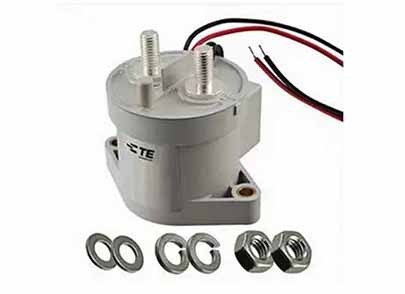
Special contactors are also available for specific applications. For example, many industrial and commercial contactor applications require switching lighting loads that have very high inrush currents that can weld a normal contactor’s contacts together. Metal halide lighting is one such load with a high inrush current requirement. Switching power supplies also present similar highly capacitive loads that draw large initial inrush currents. There are specialized contactors that incorporate NTC inrush thermistors that initially limit the current to the load and prevent the inrush of current from welding the contacts together. Alternatively, high current NTC inrush thermistors external to the contactor can be added to the power circuit to achieve the same result.
Conclusion
Relays and contactors are very effective components for switching electrical power as long as they’re specified correctly, which means getting the right coil voltage (including AC and DC) and sizing the contacts correctly. Relays are available in many form factors, while contactors which are more standardized industrial components, are available in more uniform form factors. The choice depends on the load to be switched while also taking the type of load (resistive, capacitive, or inductive) into consideration.


