


Microprocessors, FPGAs, DSPs, analog-to-digital converters (ADCs), and system-on-chip (SoC) devices typically run from multiple voltage rails. To prevent lock-ups, bus contention issues, and high inrush current, designers need these power rails to be started and shutdown in a specific order. This is a process known as power sequence control or power sequencing, and a number of solutions are available to do this effectively.
The complex devices that require voltage sequencing may have voltage rails for the core and analog blocks that need to be powered up before the digital I/O rails. Some designs may necessitate different sequences, but in any case, proper power-up and power-down sequencing is required to avoid issues.
The various power sequencers, monitors, and supervisors that have emerged to provide effective ramp up and shutdown have also adopted techniques to monitor voltage and current levels to calculate power levels in order to protect complex integrated circuits and subassemblies.
This article will explain the details of power sequencing, discuss power sequence specifications and techniques, and how to apply power sequencers to achieve specified power rail timing and sequencing.
Why worry about power sequencing?
FPGAs and similar complex ICs are broken down internally into many power domains. Most of these ICs require a specific order when starting up or shutting down the device. For example, FPGAs generally power the core logic, I/O, and auxiliary circuits separately.
The core typically comprises the processor and logic foundation of the FPGA. This domain is characterized by a low voltage and high current power profile. Due to the extremely low voltage, there are very high accuracy requirements, and due to the dynamic nature of the digital load, transient performance must be excellent. The I/O represents the various inputs and outputs of the FPGA. Voltage requirements depend on the type of interface. In general the voltage levels will be greater than those of the core. Current demand varies depending on the type, number and speed of the I/O.
Auxiliary circuitry comprises the noise-sensitive analog circuits in an FPGA, such as phase-locked loops (PLLs) and other analog circuit elements. Current requirements are reasonably low, but ripple voltage is a major concern and must be minimized. Ripple in the analog sections can result in excessive jitter and phase noise in PLLs, and spurious responses in amplifiers.
Starting up the power supplies for each domain in the incorrect order can cause problems and can result in damage to the FPGA. Consider that the I/O section is based on transmitting and receiving data on a tristate bus. The I/O control is handled by the core. If the I/O domain is powered on before the core, the I/O pins end in indeterminate states. If the external bus components are powered up, there may be bus contention resulting in high currents in the I/O drivers. As such, the core should be brought up before the I/O domain. It is important to consult the supplier’s specification for the FPGA to learn the recommended sequence of power application and shutdown, as well as the maximum differential voltages between power rails.
Similarly, devices like power operational amplifiers have two power domains: the analog domain and the digital domain. The digital domain supplies power to the amplifiers’ diagnostic status flags for over-temperature and overcurrent states. The digital domain also supports the amplifier enable/shutdown functionality. The device specification requires that the digital domain be powered up prior to the analog supply so that these status flags are functional before the analog domain is powered on. This is to prevent possible damage to the device.
Power sequence methodology
There are three common types of multi-rail sequencing (Figure 1). The most common is sequential where one supply rail is turned on first, followed by a delay before the next rail is turned on. The delay is set so that the first rail reaches regulation before the second rail is started.
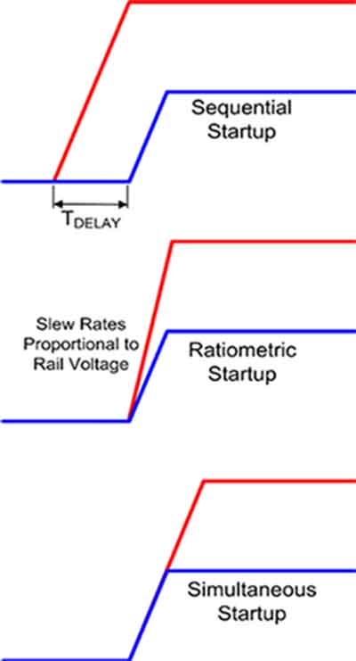
The second sequencing technique is ratiometric. In this technique, the rails start up at the same time and reach their rated voltages at the same time. This requires that the rise time of the rails be proportional to the rail voltage in order to achieve regulation at the same time.
Some devices may not tolerate the instantaneous voltage differences occurring before regulation is reached. It can lead to the device drawing higher current from one supply during this period.
The third approach, simultaneous startup, minimizes instantaneous differences in voltages. This technique lessens the scale and period of these stresses. A common way of implementing this method is simultaneous power up, in which the voltage rails rise together and at the same rate, with the higher rail, usually the I/O voltage rail, continuing after the lower or core voltage rail has reached its final value.
Regardless of the technique used, the voltages must rise monotonically. Failing this, the device may not initialize correctly due to an unexpected drop in the voltage during startup.
Additionally, soft start may be applied to limit inrush currents during startup. This practice limits the current during startup, permitting gradual charging of the capacitance of the power rail on startup.
Power supply shutdowns are generally specified to occur in the reverse order from the startup.
The choice of startup or shutdown technique to use depends on the device’s specifications.
Power supply sequencing examples
Simultaneous startup is relatively easy to setup. The highest voltage output is connected to the input(s) of the lower voltage regulator(s) (Figure 2).
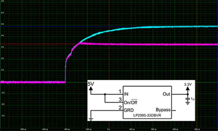
In this example the higher voltage is the 5 volt supply. This is fed into the 3.3 volt regulator as well. The 5 volt and 3.3 volt outputs are shown as they rise simultaneously with a minimum voltage difference up to the regulation point of the 3.3 volt supply.
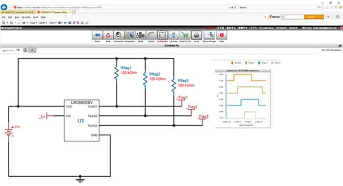
The sequential technique is best implemented using a sequencer integrated circuit such as the LM3880 from Texas Instruments. The LM3880 is a simple power supply sequencer that can control multiple independent regulators or power supplies using their enable inputs.
The LM3880, when enabled, will sequentially release its three output flags with individual time delays between the flag. This will permit the connected power supplies to start up. During shutdown the output flags will follow a reverse sequence. A design example using the LM3880 is shown using Texas Instruments’ WEBENCH Power Designer software (Figure 3). This free software tool helps the engineer design power related circuits providing schematics, bills of materials, and simulated results. The figure shows the schematic and charts, the enable, and the three flag outputs.
The delay times and sequence order in the LM3880 are fixed, but are factory customizable using the built-in EPROM. Texas Instruments also offers a capacitor programmable delay in the LM3881 sequencer.
A slightly more sophisticated power control device is the LTC2937 sequencer/voltage supervisor from Analog Devices. Like the LM3880, the LTC2937 can control the order and time delay of up to six power supplies or regulators (Figure 4).
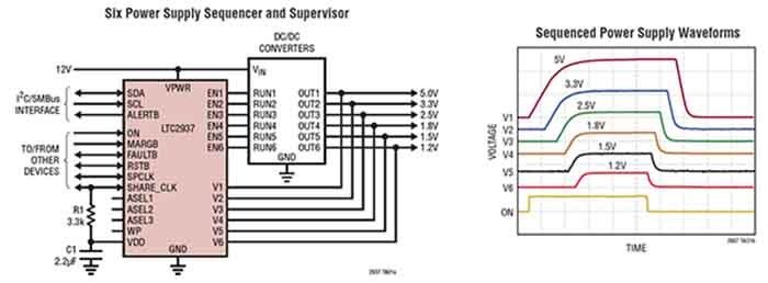
In addition to sequencing up to six power rails, it also monitors the voltages on those rails to detect over voltage, under voltage, drop outs and stalled power startups. In the event of a fault, the device can be programmed to shut down or restart the supplies. Error conditions are logged to internal EEPROM. The LTC2937 can be programmed and controlled via I2C or SMBus. Programming is supported by Analog Devices’ LTpowerPlay GUI software. The EEPROM allows autonomous operation without software. When a system requires more than six power rails, multiple LTC2937s can be chained together to control as many as 300 supplies.
For complex multicore processors, FPGA’s, and other SOC devices, Texas Instruments provides the TPS650860 configurable multi-rail power management unit. This single IC, with an input voltage range from 5.6 to 21 volts, contains three step-down controllers, three step-down converters, a sink or source low dropout (LDO) linear regulator, three low voltage input LDOs, regulators, and three load switches (Figure 5).
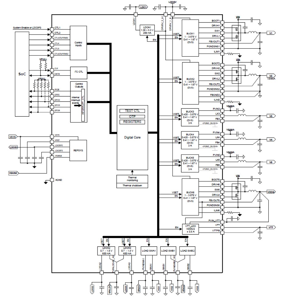
This device has 13 regulated outputs to supply the needs of the FPGA or other load device.
The buck converters include a built-in power stage, while the buck controllers require an external power stage. Both converters and controllers have integrated voltage sensing inputs to monitor the supply outputs, which can be controlled for sequencing. The load switches include slew rate control, permitting programming of the rails associated with these switches for any of the three sequence types, sequential, ratiometric, or simultaneous.
The TPS650860 is controlled via an I2C interface allowing simple control either by an embedded controller or by an associated SoC manager. This power management IC offers leading-edge control flexibility.
Conclusion
There are multiple methods to control the order of power startup or shutdown varying from very simple to very intricate. These differ in the number of rails controlled, precision, and range of control functions, as well as the cost.


 combined with superior switching performance")


