


SCOPE
This application note covers the details in using the ADRV9040 for multiband applications. More details on the ADRV9040 are available in datasheet, system development user guide (SDUG), and various application notes in Appendix section.
INTRODUCTION
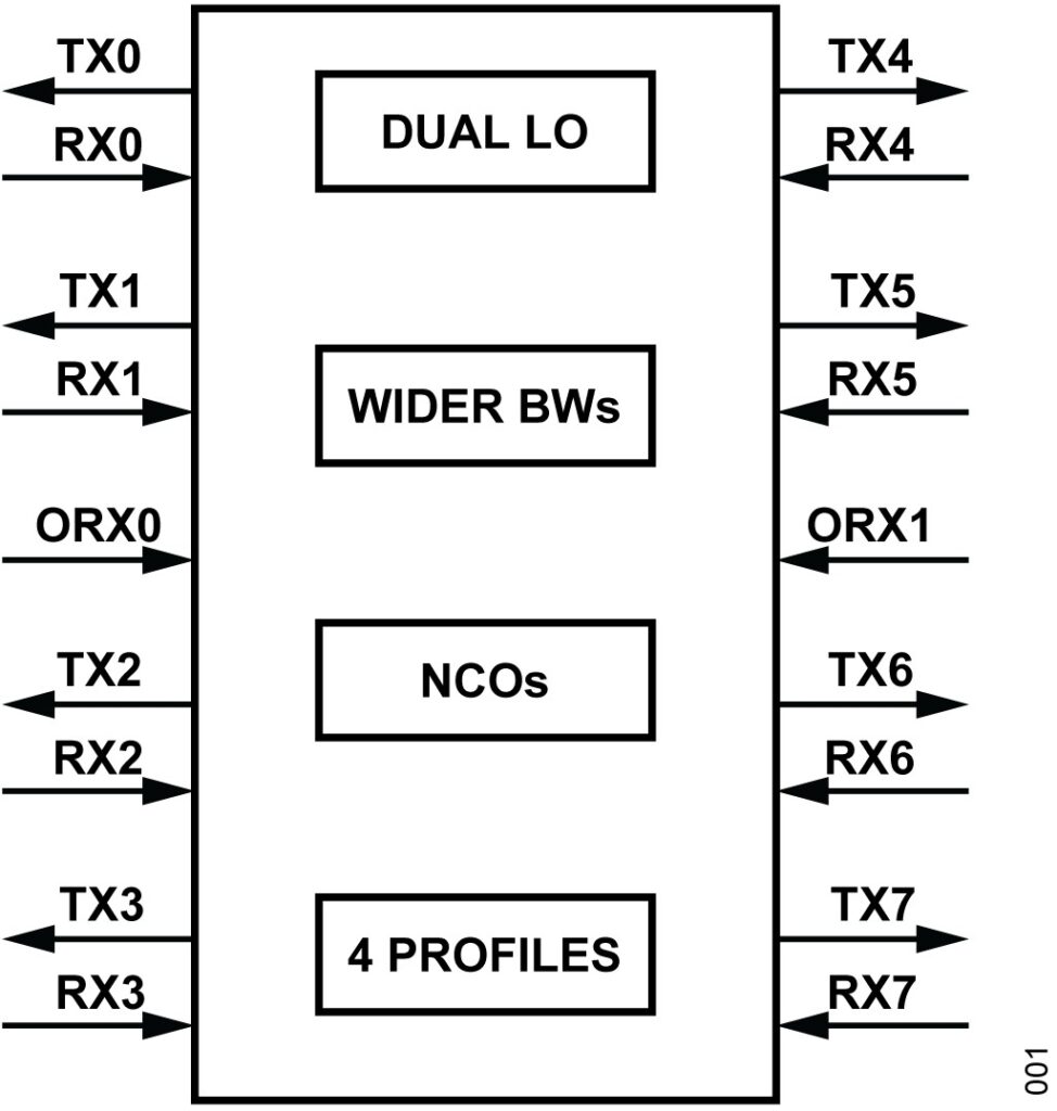
In the ADRV9040 8T8R2O RF transceiver, multiband capability is enabled by dual LO functionality and their additional LO dividers within the path, which allows wideband operation of the receiver and transmitter channels. This allows 4 individual band profiles within the tunable range, it maximizes use case flexibility. Figure 1 shows the overview of its features which enable multiband operation.
MULTIBAND INTRODUCTION
The ADRV9040 transceiver supports 8T8R2ORX channels which are independent to each other. However, in some cases, users may not need all 8 transmitter/receiver channels working for the same band depending on the data rate, deployment scenarios and they may have license for other bands as well which means customers can have multibands in the same RRH/ RU without the need of going for an additional RU that must support other bands. Instead of using 8T8R single band, user can configure 2x 4T4R in a single RRH or 4x 2T2R band combinations as required.
ADRV9040 FOR MULTIBAND APPLICATIONS.
The ADRV9040 supports multiband due to its important features as defined below:
► Supports dual LO with variable root and leaf dividers, its ability to multiplex the LO to different transmitter, receiver, and ORX channels
► Wider RF bandwidths for transmitter, receiver, and observation receiver channels
► NCOs with in BDUC/BDDC, CDUC/CDDC blocks
► Ability to configure 4 different profiles
As the ADRV9040 supports wider bandwidth (BW) of 400MHz, if two bands are close to each other and if the front end supports a wider BW combining both the bands which falls within the support- ed 400MHz BW, there are no changes in the radio small signal design,which is an added advantage.
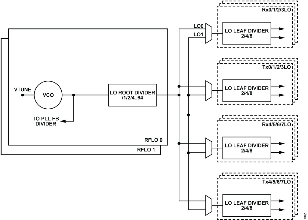
DUAL LO WITH VARIABLE ROOT AND LEAF DIVIDERS
A highly configurable LO generation network is implemented in the device to provide flexibility in LO assignment for the two RF LO sources. The LOGEN network is shown in Figure 2 and consists of a root divider located close to the RF voltage controlled oscillator (RFVCO) and separate leaf dividers located at each receiver and transmitter slice. The root divider ratio is from 1/2/4/8/16/32 64 in binary steps. The leaf divider range is 2/4/8. This setup allows the generation of power of two LO in each transmitter and receiver path and also non-power of 2 LOs in either 4T4R section.


 combined with superior switching performance")


