


Objective
In this laboratory, we continue our discussion on operational amplifiers (see the previous lab “ADALM2000 Simple Op Amps”), focusing on variable gain/voltage con- trolled amplifiers. Most operational amplifier (op amp) circuits have a fixed level of gain. However, it is often advantageous to vary the gain. This can be done simply by using a potentiometer on the output of a fixed-gain op amp circuit, but sometimes it may be more useful to vary the gain of the amplifier circuit itself. A variable gain or voltage controlled amplifier is an electronic amplifier that varies its gain depending on a control voltage. This type of circuit has many applications, including audio level compression, synthesizers, and amplitude modulation. It can be realized by first creating a voltage controlled resistor, which is used to set the amplifier gain. The voltage controlled resistor is one of the numerous circuit elements that can be produced by using a transistor with simple biasing. Another approach is to use potentiometers to vary the value of the resistors that set the gain of the amplifier.
Materials
- ADALM2000 Active Learning Module
- Solderless breadboard and jumper wire kit
- Two 1 kΩ resistors
- One 4.7 kΩ resistor
- Three 10 kΩ resistors
- One 10 kΩ potentiometer
- One OP97 operational amplifier
- One 2N3904 NPN transistor
Voltage Controlled Amplifier Using a Transistor Background Consider the circuit schematic presented in Figure 1.
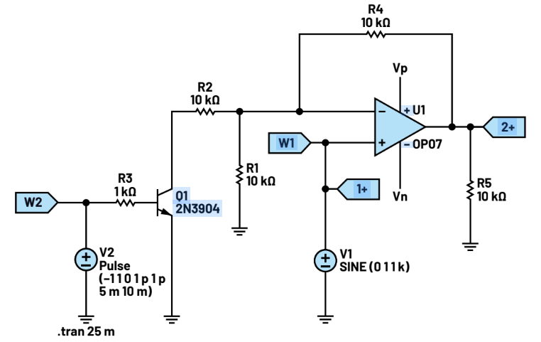
The configuration of the circuit is similar to a basic non-inverting amplifier. The only addition consists of a transistor and a resistor in parallel with resistor R2. The transistor works as a switch that allows two gain settings, based on its cur- rent state (on/off).
Read the full article here.


 combined with superior switching performance")


