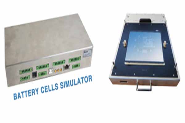
The next-generation batteries offer thrilling performances in terms of capacity and reduced charge and discharge times. Most of the credit must be given to the chemistry of the Lithium-Ion cells (NMC, LFP) and the electrode structure. However, this performance requires accurate supervision and management of the individual cells through a Battery Management System (BMS). These systems are capable of monitoring all of the parameters of each cell, and, if necessary, actively taking action to balance them.
Let’s analyze in detail the activities and capabilities of the BMS system
The first parameter that the BMS should monitor is temperature, which is essential for safety. All cells have an ideal temperature range, outside of which performances rapidly decay. The temperature should never reach values that are too high, which could lead to a thermal runaway situation, with a consequent risk of fire and/or explosion. If temperatures outside of the safety parameters are detected, the BMS quickly stops the charging or discharging process.
The second potential critical point which is monitored by the BMS concerns the management of the charge/discharge process, which determines the life of the battery; in fact, each cell must never be overcharged or over-discharged. This could irreversibly damage the cell, ruining the entire module.
It is important to take into account that a standard automotive battery is normally made up of dozens of modules and, in turn, each module is made up of a significant and variable number of cells, (dozens if prismatic, hundreds if cylindrical) connected in series and/or in parallel. Each module is mechanically enclosed, often even molded, and therefore difficult to rework or repair.
The charge/discharge condition of an entire battery ends when the “single cell” reaches full charge/discharge, not when, as one might think, all of the cells are charged/discharged; this prevents overstressing the cells. Therefore, aiming to avoid, for example, that a “single cell”, charged at 50% (when all the other cells are at 100%), affects the energy supply capacity of the entire battery, the BMS takes care of balancing the charge of each “single cell”.
The BMS can operate with active or passive balancing. In the first case, the balancing process makes sure that the cells are charged in equal percentages, shifting the charge among them as needed, with an evident improvement of overall efficiency. In the second case, instead, the system discharges the cells that have a higher charge than the others, a process that is easy to implement but results in an obvious waste of energy.
To monitor and modify when necessary, the BMS measures the voltage of the individual cell and the Coulomb current, aiming to determine the State of Charge (SoC) and the State of Health (SoH), essential parameters in monitoring the life of the battery.
Given the importance of the BMS to the life cycle of the entire battery system, it becomes obvious that a functional test of the BMS itself needs to include the verification of all of its performances and functions. A functional test could involve the use of all the actual cells in a battery but, besides the practical difficulties related to the high number of cells, this approach would not ensure repetitive and accurate test conditions, and would also lack flexibility. For this reason, the use of battery cell simulators in the functional test of the BMS is the recommended approach.
To be able to provide the conditions necessary for the functional test of the BMS, a battery cell simulator should be able to generate a programmable floating voltage in the range of 0 – 5 V, to simulate the cell in the rated, as well as under/over voltage conditions.

The following chart shows the voltage-charge curve of a typical Lithium-Ion cell and illustrates how even very small variations (fractions of an mV) can account for large differences in the SoC of the cell. Consequently, a battery cell simulator must have the capability to generate voltage with the required accuracy, as well as be able to measure the real voltage output.
Seica’s Compact BMS represents the ideal solution for a complete test of a Battery Management System: not only is it equipped with a battery cell simulator that is specifically designed for the purpose, but it provides the integrated architecture and capabilities for
in-circuit (ICT) and functional testing in a manufacturing environment. While ICT testing ensures the integrity of each electronic component in the BMS, providing precise diagnostic selectivity, functional testing ensures that each unit meets all of its operational requirements.

The Compact BMS has been designed and manufactured to handle typical voltages of 500/600 V, and in some cases up to 1000 V, since it may be necessary to simulate a series of hundreds of cells.
In those cases where measuring the voltage of the individual cell is not sufficient to determine the charge and health conditions of the cells (SoC and SoH), the Seica simulator enables the Coulomb Current Measurement, which measures the current output, repeatably and at set time intervals, then sums up the measurements to calculate the total amount of energy during charging or discharging.
To simulate passive and active balancing conditions, the Seica Compact BMS simulator can source or sink a current (programmable and measurable by the simulator itself) up to ±5 A.
To avoid wasting energy, ideally the Battery Management System should not take current from the cell (it must not discharge it). To test this function, the Compact BMS handles and accurately measures any current (generally microamperes) absorbed by the BMS. Since the BMS must detect any cell fault conditions, such as short circuits, a disconnected wire or polarity inversions, Seica’s test solution can also correctly simulate these measurement conditions.
For testing the temperature measurement function of the BMS, which typically uses NTC/PTC thermistors, the Compact BMS battery cell simulator can provide variable resistance, ranging from tens of Ohms to MOhms.
When it is necessary to simulate hundreds of cells, system costs can skyrocket. To maintain the cost-effectiveness of the solution, the Compact BMS provides an interesting multiplexing solution with the 3D version of the S64 matrix, a solution made possible thanks to the scalability and flexibility of the architecture of Seica’s test platform, specifically designed for the test requirements in a manufacturing environment.
In short, the Compact BMS is the solution that can simulate the full operating conditions of any BMS, providing the stimuli and measurements needed to test all of its capabilities and functions.


