


Health Monitoring Is Going Wearable
When I was a little boy, my mom always made sure that I had enough change to make a phone call in case of emergency. Twenty years later, mobile phones allowed us to make calls at any time and place. After another 20 years of innovation, the phone is no longer the key feature of our smart devices, which can take beautiful pictures, stream audio and video, provide access to a wide variety of services—and are now becoming our personal trainers. The devices, loaded with sensors or connected to bodily worn sensors, monitor day-to-day activity and personal health. An increasing awareness of our health has fueled interest in measuring vital parameters—such as heart rate, temperature, oxygen saturation, blood pressure, activity level, and calories burned—and following their daily trends.
Now, a universal sensor front end with multiple sensors can monitor these parameters. The biggest challenges are to minimize size and maximize battery lifetime. This article discusses solutions for the rapidly growing market for wearable electronics.
The Most Important Vital Sign
Without a heartbeat we would be in serious trouble, so pulse or heart rate is by far the most important parameter to be monitored. In addition to the number of beats per minute, we want to check the behavior of the heart as a function of activity. The rhythm is also important, as rapidly changing heart rates are a sign of cardiac disease.
Monitoring heart rate and heart activity is classically done by measuring biopotential with an electrocardiogram (ECG). Electrodes connected to the body measure signals caused by electric activity in the cardiac tissue. This principle is used in professional diagnostic systems, where up to 10 electrodes can be connected to the chest and limbs. ECGs provide detailed information regarding the various components (P-, QRS-, and T-wave) of one heartbeat.

Single-lead ECGs are more common in the sports world, with a two-electrode chest strap measuring heart activity. ECG waveforms can be detected, but most systems just measure heart rate. These straps are uncomfortable, so the sports and wellness industry is looking for alternatives, such as integrating the electrodes into a sport shirt. The AD8232 single-lead heart rate monitor front end, shown in Figure 1, was developed for this kind of low-power wearable application. It includes an instrumentation amplifier with a gain of 100 V/V and a high-pass filter to block the offset voltage generated by the half-cell potential of the electrodes on the skin. An output buffer and low-pass filter reject the high-frequency component generated by muscle activity (EMG signals). This low-power front end, which draws 170 μA, can be used with the ADuCM350 16-bit meter-on-a-chip to perform high-performance, single-lead ECG measurements.
New Method for Measuring Heart Rate
A new trend for measuring heart rate is the photoplethysmogram (PPG), an optical technique that retrieves cardiac information without measuring the biopotential. PPG has mainly been used to measure blood oxygen saturation (SpO2), but can provide cardiac information without a biopotential measurement. With PPG technology, heart-rate monitors can be integrated in wearable devices such as wristwatches or bracelets. This is not possible with biopotential systems due to the tiny signal levels.
In optical systems, light is transmitted through the surface of the skin. Light absorbed by the red blood cells is measured with a photosensor. As the heart beats, the changing blood volume scatters the amount of light received. When measured on a finger or earlobe, where considerable arterial blood is available, a red or infrared light source provides the best accuracy. Arteries are rarely located on top of the wrist, however, so with wrist worn devices, pulsatile components must be detected from veins and capillaries just under the surface of the skin, making green light better.
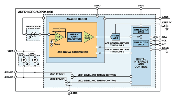
The ADPD142 optical module, shown in Figure 2, features a complete photometric front end, with integrated photosensor, current sources, and LEDs. Designed for reflective measurement, it can be used to implement a PPG measurement. All components are mounted in a small module.
Challenges with Optical VSM
The main challenges for measuring PPG on a wrist-worn device are due to ambient light and motion-generated artifacts. The Sun, which generates dc errors, is relatively easy to cancel out, but light from fluorescent and energy-saving lamps carry frequency components that cause ac errors. The analog front end uses two structures to reject interferers from dc to 100 kHz. After the analog signal conditioning, a 14-bit, successive-approximation analog-to-digital converter (ADC) digitizes the signal, which is transmitted via an I2C interface to a microcontroller for final post processing.
A synchronized transmit path is integrated in parallel with the optical receiver. Its independent current sources can drive two separate LEDs with current levels programmable up to 250 mA. The LED currents are pulsed, with pulse lengths in the microsecond range, so the average power dissipation is kept low to maximize battery lifetime.
The LED driving circuit is dynamic and configurable on-the-fly, making it independent of environmental conditions such as ambient light, the tint of the wearer’s skin and hair, or sweat between the sensor and the skin that would otherwise decrease sensitivity. The excitation LEDs can be configured easily to build an autoadaptive system. All timing and synchronization is handled by the analog front end, so no overhead is required from the system processor.
Two versions of the ADPD142 are available: the ADPD142RG integrates red and green LEDs to support optical heart-rate monitoring; and the ADPD142RI integrates red and infrared LEDs for oxygen saturation (SpO2) measurement.
Influence of Motion
Motion also disturbs optical systems. When optical heart-rate monitors are used for sleep studies, this may not be an issue, but sport watches and bracelets worn during exercise have a hard time cancelling out motion artifacts. Motion between the optical sensors (LED and photodetector) and the skin will decrease the sensitivity of the optical signal. In addition, the frequency components of the motion might be seen as a heart- rate measurement, so the motion must be measured and compensated. The tighter the device is attached to the body, the lower the impact, but it is nearly impossible to cancel this out mechanically.
Various methods are used to measure motion. One is optical, using multiple LED wavelengths. The common signals indicate motion, while the differential signals detect the heart rate. It’s better to use a real motion sensor, however. Not only will this allow accurate measurement of motion applied to the wearable device, but it can also be used for additional features, such as tracking activity, counting steps, or starting an application when a certain g-force is detected.
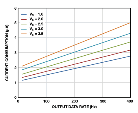
The ADXL362 micropower, 3-axis MEMS (microelectromechanical system) accelerometer is ideal for sensing motion in battery-operated wearable applications. Its 12-bit ADC converts acceleration into a digital signal with 1-mg resolution. The power consumption dynamically scales with the sampling rate, and is only 1.8 μA with a 100-Hz output data rate and 3.0 μA at 400 Hz. These higher data rates are useful for user interface, such as tap/double-tap detection.
For starting an application when motion is detected, high-speed sampling is not needed, so that the data rate can be reduced to 6 Hz, resulting in an average power consumption of 300 nA. This makes this sensor attractive for low-power applications and implantable devices, in which batteries cannot be replaced easily. The ADXL362 is available in a 3.0-mm × 3.25-mm package. Figure 3 shows the supply current vs. output data rate for several supply voltages.
Connecting the Sensors in the System
The heart of the system that connects all these sensors, runs the required software, and stores, displays, or transmits the results is the ADuCM350 mixed-signal meter-on-a-chip, which integrates a high-performance analog front end (AFE) with a 16-MHz ARM® Cortex®-M3 processor core, as shown in Figure 4. The flexibility of the AFE and rich feature set of the microprocessor make this chip ideal for portable and wearable applications. The configurable AFE allows it to be used with nearly any sensor, and its programmable waveform generator powers analog sensors with ac or dc signals. The high-performance receive signal chain conditions sensor signals and converts them to digital with a true 16-bit, 160-kSPS ADC, which features ±1-LSB max INL and DNL, and no missing codes. It can be used with any type of input signal, including voltage, current, potentiostat, photocurrent, and complex impedance.

The AFE can be operated in standalone mode without involvement of the Cortex-M3 processor. A programmable sequencer controls the measurement engine, with results stored into memory via DMA. Before starting a measurement, a calibration routine can be performed to correct offset and drift errors in the transmit-and-receive signal chains. For complex impedance measurements such as blood glucose, body mass index (BMI), or tissue discrimination applications, a built-in DSP accelerator provides a 2048-point, single-frequency discrete Fourier transform (DFT) without involvement of the M3 processor. These high-performance AFE features make the ADuCM350 unique vs. other integrated solutions.
The Cortex processor supports various communication ports including I2S, USB, MIPI, and an LCD display driver (static). In addition, it includes flash memory, SRAM, and EEPROM, and supports five different power modes to maximize battery life.
Designed for use with ultralow-power sensors, the ADuCM350 is limited to low-speed devices. Applications that require more processing power could use M3 cores that operate up to 80 MHz or Cortex-M4 processor cores.
What About Power?
Power is always a critical factor in portable and wearable devices. The devices described in this article are designed for high performance, small size, and low power, but integrating everything, including the battery, in a small package is still a challenge. Despite new battery technologies that bring more capacity per mm3, the battery is still large compared to the electronics.
Energy harvesting can reduce battery size and extend battery life. Various technologies are used to harvest energy, including thermoelectric, piezoelectric, electromagnetic, and photovoltaic, with light and heat being the most appropriate for wearable devices. The sensors usually don’t provide a lot of output power, so every joule generated should be caught and used. The ADP5090 ultralow-power boost regulator, shown in Figure 5, bridges the gap between harvester and battery. This efficient switch-mode power supply boosts input voltages from as low as 100 mV up to 3 V. During a cold start, with the battery completely discharged, a 380-mV minimum input voltage is required, but in normal operation, where either the battery is not completely drawn down or some energy is left in the super capacitor, any input signal down to 100 mV can be converted to a higher potential and stored for later use.
Housed in a tiny 3-mm × 3-mm package, the chip is programmable for use with various harvester sensors. It draws 250-nA maximum quiescent current and works with almost any battery technology from Li-Ion to thin-film batteries and super capacitors. Integrated protection circuits ensure safe operation.

Conclusion
This article describes some low-power products for wearable and personal health applications, but this fast growing market is changing rapidly. ADI technology can convert challenging problems into complete products and turnkey solutions. Watch for more to come.


 combined with superior switching performance")


