


Abstract
A microprocessor can easily generate 1-Wire timing signals if a true bus master is not present (e.g., DS2480B, the family of DS2482 parts). This application note provides an example, written in ‘C’, of the basic standard-speed 1-Wire master communication routines. The four basic operations of a 1-Wire bus are Reset, Write 1 bit, Write 0 bit, and Read bit. Byte functions can then be derived from multiple calls to the bit operations. The time values provided produce the most robust 1-Wire master for communication with all 1-Wire devices over various line conditions.
Introduction
A microprocessor can easily generate 1-Wire timing signals if a dedicated bus master is not present. This application note provides an example, written in ‘C’, of the basic standard-speed 1-Wire master communication routines. Overdrive communication speed is also covered by this document. There are several system requirements for proper operation of the code examples:
- The communication port must be bidirectional, its output is open-drain, and there is a weak pullup on the line. This is a requirement of any 1-Wire bus. See Category 1 in application note 4206, “Choosing the Right 1-Wire Master for Embedded Application” for a simple example of a 1-Wire master microprocessor circuit.
- The system must be capable of generating an accurate and repeatable 1µs delay for standard speed and 0.25µs delay for overdrive speed.
- The communication operations must not be interrupted while being generated.
The four basic operations of a 1-Wire bus are Reset, Write 1 bit, Write 0 bit, and Read bit. The time it takes to perform one bit of communication is called a time slot in the device data sheets. Byte functions can then be derived from multiple calls to the bit operations. See Table 1 below for a brief description of each operation and a list of the steps necessary to generate it. Figure 1 illustrates the waveforms graphically. Table 2 shows the recommended timings for the 1-Wire master to communicate with 1-Wire devices over the most common line conditions. Alternate values can be used when restricting the 1-Wire master to a particular set of devices and line conditions. See the downloadable worksheet to enter system and device parameters to determine minimum and maximum values.
| Operation | Description | Implementation |
| Write 1 bit | Send a ‘1’ bit to the 1-Wire slaves (Write 1 time slot) | Drive bus low, delay A Release bus, delay B |
| Write 0 bit | Send a ‘0’ bit to the 1-Wire slaves (Write 0 time slot) | Drive bus low, delay C Release bus, delay D |
| Read bit | Read a bit from the 1-Wire slaves (Read time slot) | Drive bus low, delay A Release bus, delay E Sample bus to read bit from slave Delay F |
| Reset | Reset the 1-Wire bus slave devices and ready them for a command | Delay G Drive bus low, delay H Release bus, delay I Sample bus, 0 = device(s) present, 1 = no device present Delay J |
| Parameter | Speed | Recommended (µs) |
| A | Standard | 6 |
| Overdrive | 1.0 | |
| B | Standard | 64 |
| Overdrive | 7.5 | |
| C | Standard | 60 |
| Overdrive | 7.5 | |
| D | Standard | 10 |
| Overdrive | 2.5 | |
| E | Standard | 9 |
| Overdrive | 1.0 | |
| F | Standard | 55 |
| Overdrive | 7 | |
| G | Standard | 0 |
| Overdrive | 2.5 | |
| H | Standard | 480 |
| Overdrive | 70 | |
| I | Standard | 70 |
| Overdrive | 8.5 | |
| J | Standard | 410 |
| Overdrive | 40 |
Worksheet to calculate these values is available for download.
Code Examples
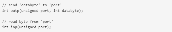
This following code samples rely on two common ‘C’ functions outp and inp to write and read bytes of data to input/output (I/O) port locations. They are typically located in the <conio.h> standard library. These functions can be replaced by platform appropriate functions.
The constant PORTADDRESS in the code (Figure 3) is defined as the location of the communication port. The code assumes bit 0 of this location controls the 1-Wire bus. Setting this bit to 0 drives the 1-Wire line low. Setting this bit to 1 releases the 1-Wire to be pulled up by the resistor pullup or pulled down by a 1-Wire slave device.
The function tickDelay in the code is a user-generated routine to wait a variable number of 1/4 microseconds. This function varies for each unique hardware platform running so it is not implemented here. Below is the function declaration for the tickDelay along with a function SetSpeed to set the recommended standard and overdrive speed tick values.
Example 1. 1-Wire Timing Generation
| // Pause for exactly ‘tick’ number of ticks = 0.25us void tickDelay(int tick); // Implementation is platform specific // ‘tick’ values int A,B,C,D,E,F,G,H,I,J; //—————————————————————————– // Set the 1-Wire timing to ‘standard’ (standard=1) or ‘overdrive’ (standard=0). // void SetSpeed(int standard) { // Adjust tick values depending on speed if (standard) { // Standard Speed A = 6 * 4; B = 64 * 4; C = 60 * 4; D = 10 * 4; E = 9 * 4; F = 55 * 4; G = 0; H = 480 * 4; I = 70 * 4; J = 410 * 4; } else { // Overdrive Speed A = 1.5 * 4; B = 7.5 * 4; C = 7.5 * 4; D = 2.5 * 4; E = 0.75 * 4; F = 7 * 4; G = 2.5 * 4; H = 70 * 4; I = 8.5 * 4; J = 40 * 4; } } | |
Example 2 below shows the code examples for the basic 1-Wire operations.
Example 2. 1-Wire Basic Functions
| //—————————————————————————– // Generate a 1-Wire reset, return 1 if no presence detect was found, // return 0 otherwise. // (NOTE: Does not handle alarm presence from DS2404/DS1994) // int OWTouchReset(void) { int result; tickDelay(G); outp(PORTADDRESS,0x00); // Drives DQ low tickDelay(H); outp(PORTADDRESS,0x01); // Releases the bus tickDelay(I); result = inp(PORTADDRESS) ^ 0x01; // Sample for presence pulse from slave tickDelay(J); // Complete the reset sequence recovery return result; // Return sample presence pulse result} //—————————————————————————– // Send a 1-Wire write bit. Provide 10us recovery time. // void OWWriteBit(int bit) { if (bit) { // Write ‘1’ bit outp(PORTADDRESS,0x00); // Drives DQ low tickDelay(A); outp(PORTADDRESS,0x01); // Releases the bus tickDelay(B); // Complete the time slot and 10us recovery } else { // Write ‘0’ bit outp(PORTADDRESS,0x00); // Drives DQ low tickDelay(C); outp(PORTADDRESS,0x01); // Releases the bus tickDelay(D); } } //—————————————————————————– // Read a bit from the 1-Wire bus and return it. Provide 10us recovery time. // int OWReadBit(void) { int result; outp(PORTADDRESS,0x00); // Drives DQ low tickDelay(A); outp(PORTADDRESS,0x01); // Releases the bus tickDelay(E); result = inp(PORTADDRESS) & 0x01; // Sample the bit value from the slave tickDelay(F); // Complete the time slot and 10us recovery return result;} | |
This is all for bit-wise manipulation of the 1-Wire bus. The above routines can be built upon to create byte-wise manipulator functions as seen in Example 3.
Example 3. Derived 1-Wire Functions
| //—————————————————————————– // Write 1-Wire data byte // void OWWriteByte(int data) { int loop; // Loop to write each bit in the byte, LS-bit first for (loop = 0; loop < 8; loop++) { OWWriteBit(data & 0x01); // shift the data byte for the next bit data >>= 1; }} //—————————————————————————– // Read 1-Wire data byte and return it // int OWReadByte(void) { int loop, result=0; for (loop = 0; loop < 8; loop++) { // shift the result to get it ready for the next bit result >>= 1; // if result is one, then set MS bit if (OWReadBit()) result |= 0x80; } return result;} //—————————————————————————– // Write a 1-Wire data byte and return the sampled result. // int OWTouchByte(int data) { int loop, result=0; for (loop = 0; loop < 8; loop++) { // shift the result to get it ready for the next bit result >>= 1; // If sending a '1' then read a bit else write a '0' if (data & 0x01) { if (OWReadBit()) result |= 0x80; } else OWWriteBit(0); // shift the data byte for the next bit data >>= 1; } return result;} //—————————————————————————– // Write a block 1-Wire data bytes and return the sampled result in the same // buffer. // void OWBlock(unsigned char *data, int data_len) { int loop; for (loop = 0; loop < data_len; loop++) { data[loop] = OWTouchByte(data[loop]); }} //—————————————————————————– // Set all devices on 1-Wire to overdrive speed. Return ‘1’ if at least one // overdrive capable device is detected. // int OWOverdriveSkip(unsigned char *data, int data_len) { // set the speed to ‘standard’ SetSpeed(1); // reset all devices if (OWTouchReset()) // Reset the 1-Wire bus return 0; // Return if no devices found // overdrive skip command OWWriteByte(0x3C); // set the speed to 'overdrive' SetSpeed(0); // do a 1-Wire reset in 'overdrive' and return presence result return OWTouchReset();} | |
The owTouchByte operation is a simultaneous write and read from the 1-Wire bus. This function was derived so that a block of both writes and reads could be constructed. This is more efficient on some platforms and is commonly used in API’s provided by Maxim. The OWBlock function simply sends and receives a block of data to the 1-Wire using the OWTouchByte function. Note that OWTouchByte(0xFF) is equivalent to OWReadByte() and OWTouchByte(data) is equivalent to OWWriteByte(data).
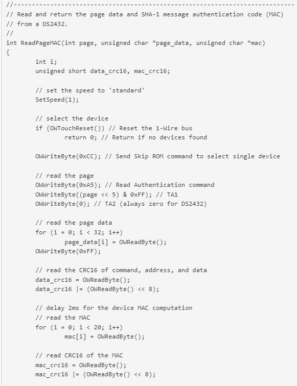
These functions plus tickDelay are all that are required for basic control of the 1-Wire bus at the bit, byte, and block level. The following example in Example 4 shows how these functions can be used together to read a SHA-1 authenticated page of the DS2432.
Example 4. Read DS2432 Example
Additional Software
The basic 1-Wire functions provided in this application note can be used as a foundation to build sophisticated 1-Wire applications. One important operation omitted in this document is the 1-Wire search. The search is a method to discover the unique ID’s of multiple 1-Wire slaves connected to the bus. Application note 187, “1-Wire Search Algorithm” describes this method in detail and provides ‘C’ code that can be used with these basic 1-Wire functions.
The 1-Wire Public Domain Kit contains a large amount of device-specific code that builds upon what has been provided here.
For details on other resources see application note 155, “1-Wire Software Resource Guide Device Description.”
Alternatives
There are several 1-Wire master chips that can be used as a peripheral to a microprocessor. The DS2480B Serial 1-Wire Line Driver provides easy connectivity to a standard serial port. Similarly the DS2482-100, DS2482-101, and DS2482-800 can connect to the I²C port.
Operation of the DS2480B is described in application note 192, “Using the DS2480B Serial 1-Wire Line Driver.”
Operation of the DS2482 is described in application note 3684, “How to Use the DS2482 I²C 1-Wire Master.”
A more sophisticated 1-Wire line driver designed specifically for long lines is presented in application note 244, “Advanced 1-Wire Network Driver.”


 combined with superior switching performance")


