


Abstract
Small electronics are still expected to operate for long periods of time despite their tiny batteries. For designers, this presents a tough challenge. This application note looks at how PMICs containing DC-DC converters designed with a unique SIMO power converter architecture supports long battery life in a tiny form factor.
Introduction
Whether it’s an earbud or a smartwatch, small electronics are expected to have long runtimes. This presents a conundrum for designers, because smaller batteries obviously have less capacity. Performance expectations aside, however, power supplies for these applications must support the distinct and diverse voltage requirements of the subsystems within the design. This is where a switching regulator based on a single-inductor, multiple-output (SIMO) power converter architecture can help. A regulator with the combination of a SIMO architecture and low quiescent current can extend battery life for space-constrained electronic products.
Advantage of Buck-Boost SIMO Converters
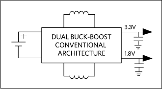
Let’s take a closer look at how a SIMO architecture works for buck-boost regulators. If we consider a traditional multiple switching-regulator topology, we can see that each switching regulator requires a separate inductor (Figure 1). Because inductors are physically large and costly, however, this approach isn’t ideal for small products. Linear regulators are another option—while they do have higher power dissipation, they are compact, fast, and low noise. There’s also a hybrid approach based on multiple low-dropout regulators (LDOs) and DC-DC converters. While this configuration yields intermediate power and heat dissipation, it also produces a larger design than LDOs alone.
The advantage of a buck-boost SIMO converter is that it can regulate up to three output voltages over wide output voltage ranges using a single inductor. The buck-boost topology also provides better output voltage ranges than a buck-only SIMO. Moreover, as one or more output voltages approaches the input voltage, the weakness of the buck-only SIMO gets magnified. At this point, a buck-only SIMO would require the inductor for too much time, affecting the other channels.
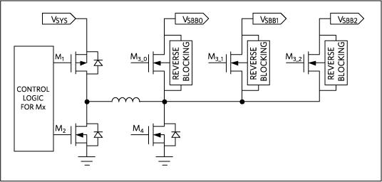
There are times when you can’t avoid having an inductor in the system. While small, an LDO can never provide a boost feature on its own. Because the SIMO architecture requires only one inductor, solutions that need at least one boost voltage are almost always better with a buck-boost SIMO. Figure 2 provides a block diagram of the SIMO architecture.
The inductor saturation current (ISAT) is a measure of electrical current when the inductance drops to 70% of its value. ISAT is determined by the inductor’s core size for a given core material and construction. As opposed to using separate DC-DC converters, the approach of using a single inductor in a SIMO architecture provides many benefits, including the following:
- Fewer high Z-height components
- Smaller footprint
- Time multiplexing, which arises when different features are often not used simultaneously. This advantage becomes apparent when the total supply current is less than the sum of the individual output requirements. For instance, consider when you have events that happen sequentially using different rail voltages. Data in some Bluetooth systems can be downloaded before it activates a function. As a result, the power associated with the radio is on at different times than the activated function(s). So, the total ISAT required for the SIMO inductor(s) used can be less than required for separate converters.
- RMS (current rating for inductors)—the channels are not time-multiplexed, but the peak power consumption of features often doesn’t happen simultaneously, which can lower the total inductor ISAT requirements
Addressing SIMO Architecture Trade-Offs
A thoughtful approach to designing with a SIMO architecture is critical for minimizing the impact of trade-offs that naturally occur with any methodology. Because a single inductor is essentially providing buckets of energy to alternate outputs, it’s not surprising that the output voltage ripple tends to be on the higher side. Also, when a SIMO is heavily loaded, it can become time-limited and there can be a delay in servicing each channel, which can further increase output voltage ripple. To help offset these sources of output voltage ripple, use larger output caps; compared to adding inductors for separate DC-DC converters, this still maintains a net footprint/BOM advantage.
Going back to our discussion of small electronic devices, such as hearables and wearables, power management ICs (PMICs) designed with micropower SIMO buck-boost DC-DC converters can provide an effective means to extend battery life. By utilizing the whole battery voltage range, as each output has the benefit of being a buck-boost configuration, such converters can create output voltages that are above, below, or equal to the input voltage. With a feature such as programmable peak inductor current for each output, the balance between efficiency, output ripple, electromagnetic interference (EMI), PCB design, and load capability for a design can be optimized.
Analog’s MAX77650 and MAX77651 PMICs were designed with micropower SIMO buck-boost DC-DC converters. The PMICs include an integrated 150mA low-dropout regulator (LDO) that provides ripple rejection for noise-sensitive applications. To minimize crosstalk and undershoot on bus signals, optional resistors (24Ω) are in series with serial data line (SDA) and serial clock line (SCL), which also safeguard device inputs from high-voltage spikes on the bus lines. Every block in these regulators has low quiescent current (1µA per output), which contributes to longer battery life. Because these PMICs always operate in discontinuous conduction (DCM) mode, the inductor current goes to zero at the end of each cycle to further minimize crosstalk and prevent oscillation. A proprietary controller in the SIMO control scheme in these converters ensures that all the outputs are serviced in a timely manner. When none of the regulators requires service, the state machine simply rests in a low-power rest state. When the controller notices that a regulator needs service, it charges the inductor until it reaches the peak current limit. Subsequently, the inductor energy discharges into the associated output until the current reaches zero. If multiple output channels require servicing simultaneously, the controller ensures that no output utilizes all of the switching cycles. Instead, the cycles interleave between all outputs that require service, skipping those outputs that don’t need service.
Power Comparison: SIMO vs. Conventional Architecture
A block diagram of the MAX77650 power tree is shown in Figure 3. Three of the four loads connect to the Li+ battery through the high-efficiency SIMO switching regulator. The fourth load is powered by the LDO from the 2.05V SIMO output,achieving 90.2% efficiency (1.85V/2.05V). Table 1 provides a comparison of the power performance between a conventional architecture and the SIMO architecture. Evaluation kits are available for both the MAX77650 and the MAX77651.
To help you explore the trade-offs associated with SIMO parameters, a SIMO calculator is available in the Design Resources tab of the MAX77650 product page. The calculator is a spreadsheet-based tool. Simply enter the system parameters in the corresponding values cell within the top section of rows in the calculator tab. The tool highlights in yellow the calculated values that are deemed to be the most interesting. If the tool determines that a parameter is outside the normal region, the tool highlights the cell in red. The comments section includes guidance on ways to enhance your design.
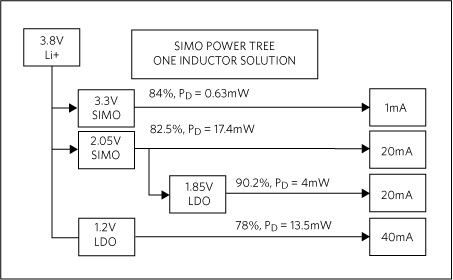
Table 1. Power Performance of SIMO Architecture vs. Conventional Architecture
| Parameter | Traditional Solution | SIMO | SIMO Advantage |
| LI+ Battery Current | 49mA | 43.4mA | SIMO saves 5.6mA |
| System Efficiency | 69.5% | 78.4% | SIMO is 8.9% more efficient |
| Minimum LI+ Battery Voltage | 3.4V due to 3.3V LDO | 2.7V | SIMO allows more discharge |
Summary
This application note examined the SIMO architecture and explained how PMICs with SIMO switching regulators can extend battery life for space-constrained electronic devices.
A similar version of this App Note appeared in Electronic Products on December 28, 2017.


 combined with superior switching performance")


