


The healthcare sector faces three major challenges: the population is growing ever older, cases of chronic diseases are increasing dramatically, and healthcare costs are exploding. The elderly population is expected to grow exponentially over the next 20 years. By 2030, ⅓ of Europeans will be older than 65 and 40% of them will require assistance. Without receiving sufficient care, the elderly are at risk of losing their independence. Therefore, independent lifestyles are highly desired by elderly people. But the independent lifestyles of older adults often come with high risks. Many smart home technologies implemented with various sensors have been developed to track and monitor the activities of elderly persons at home and assist their independent living. Buildings and urban environments equipped with sensor networks offer the elderly and sick the chance to retain their independence for longer.
Ambient assisted living (AAL) offers a range of benefits in this context. These benefits include linking patients, doctors, and medical equipment, which greatly enhances the efficiency of treatment and care. The linking enables automated recording and evaluation of patient’s activities and health data, wherever they may be. As a result, medical personnel only need to be called in if the patient’s health actually deteriorates. The goal here is to reduce costs in the healthcare sector and improve patient care—even if patients are no longer being monitored constantly in the hospital, but at home in everyday life.
Human behavior analysis and activity recognition is an integral part of today’s AAL systems. Reliable and accurate monitoring, as well as real-time actuation when needed, are must have requirements in these systems. Daily activities such as cooking, sleeping, and cleaning are good indicators of the physical capabilities of the elderly or sick. Therefore, a system that automatically recognizes these activities allows automatic health monitoring and provides an objective measure for medical staff. Such a system should be able to detect any anomalies, such as a sudden fall, and provide for an immediate actuation. An activity monitoring system is therefore a crucial step in the future health applications.
In this article, we introduce an integrated home health monitoring system that is inclusive of a vision-based, activity monitoring system and a vital sign monitoring system. The purpose of the system is to be able to monitor the activities of an individual and simultaneously be able to monitor his/her vital signs while performing that activity. The integration (binding) together of wearable healthcare technology and embedded vision technology is the key to achieving a true home health monitoring system.
Vision-Based Sensing
Until now, the activity monitoring market has been largely dominated by video surveillance technology. However, with the shift of this activity monitoring happening in home environments, video analytics fail to be the right solution due to its basic shortcomings, such as invading the privacy of the person being monitored and the amount of data load that needs to be transmitted, as it is video. The advent of embedded vision sensing technology helps overcome these two issues. An embedded vision sensing platform performs real-time processing at the edge node with the output of the system being only useful to telemetry/processed data—hence overcoming the issue of privacy, because the data being transmitted is not video or images (which invades privacy), but only activity data such as cooking, cleaning, or sleeping. Since only the telemetry data is transmitted, the reduced data rate saves on more than 90% of the bandwidth requirements, thereby saving on the cost that would be required to transmit video instead.
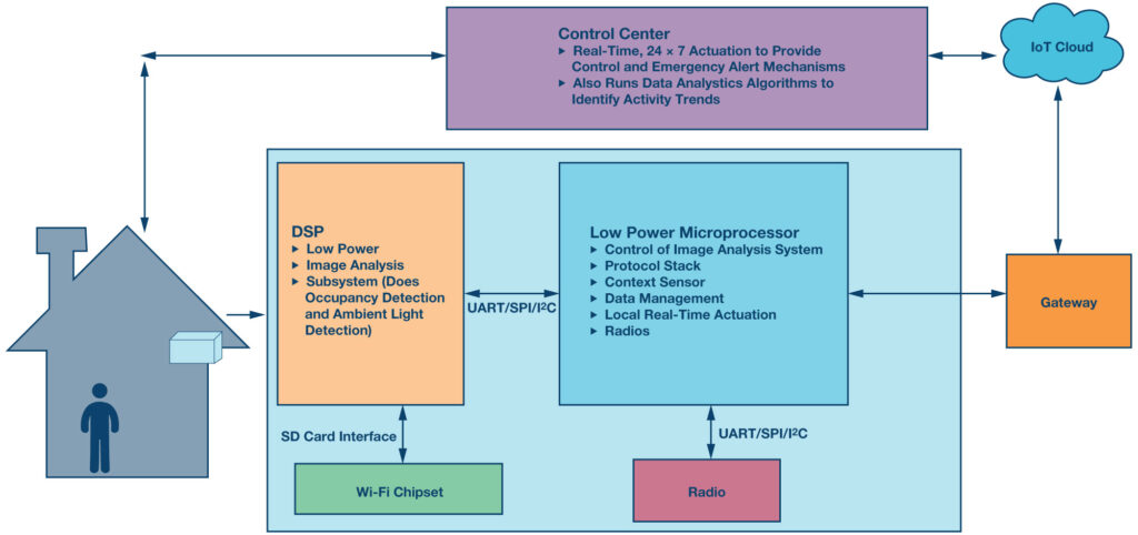
An activity monitoring embedded vision system includes detecting people, tracking people as they move, and recognizing their postures and activities of interest. The typical architecture of an embedded sensing platform would usually consist of the following:
- An optics system (a CMOS sensor plus the lens): This captures images. The right optics configuration needs to be defined on the basis of the field of view, configuration of the system, and the geometry of the room. Sometimes the CMOS sensor might do some image preprocessing, thus reducing the load of processing for the embedded processor, which, in turn, could reduce the power consumption of the system if correctly duty cycled.
- The processing system: The processor is the heart of this system and it is now expected to do a lot more controlling, sensing, and interfacing, while consuming very little power and area. The processor in an embedded system platform that runs the image processing algorithm on the image captured by the optics system. The output of the system after the processing has been achieved is just telemetry data. In a home health scenario, the output could be about the activity of the person, such as whether he/she is sleeping, cleaning, or has fallen down.
- Connectivity: This could be either wired or wireless in an embedded, vision-based system. However, it’s likely to be wireless connectivity in a home environment. Since the output is just telemetry data and not raw video data, the payload to transmit is heavily reduced. This is then transmitted over to a cloud platform and made further available in realtime in the form of an app for your nurse or guardian.
- Cloud/data analytics: This forms the back end of the system. Not only does the cloud infrastructure provide real-time access to the data in the form of an app, but it can also run background data analytics algorithms to identify trends in context with your home activities.
System Design Considerations and Major Challenges
- Reliability: It’s highly essential that an activity monitoring system provides the activity information in the most reliable, secure, and accurate fashion. Also, in case of an emergency, the system must be able to accurately detect an emergency environment and set out an alarm with a focus on reduced false alarm generation in order to prevent accidentally contacting personnel or emergency dispatch.
- Latency: An immediate response/actuation/alarming of alarms generated by your activity monitoring system is a feature that defines the exact potential of your security system. The basic functionality of monitoring your activity—be it sleeping, walking, cleaning, or a case of emergency—should be reported in an instantaneous manner so that a minimum time delay can be achieved between the occurrences and reporting.
- Tamper Proof: Lastly, an activity monitoring system needs to be as tamper proof as possible. Tampering can occur at any stage of the system, be it the end node, wireless/wired connectivity, or at the data control and analytics end of the cycle. Breach of building automation systems/networks is a topic of great concern in security systems and home monitoring systems.
Analog Devices Embedded Vision Sensing Platform
ADI’s BLIP (Blackfin low power imaging platform) is a low cost, low power, high performance embedded vision sensing platform that can run a vast array of real-time sensing and image processing algorithms. BLIP consists of the Blackfin series of processors from Analog Devices, the ADSP-BFxxx, which are aptly suited for embedded vision sensing algorithms.
Accurate, Compact, and Low Power Vital Sign Measurements
At the CES show in Las Vegas in early January 2016 that Analog Devices showed this solution for the first time. The measurement of vital signs (VSM) presented included heart rate and activity, and it was shown by a watch that is worn on the wrist.
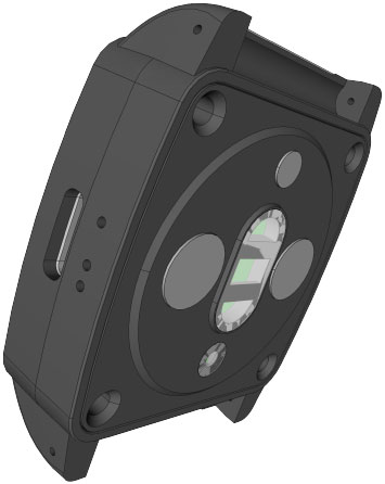
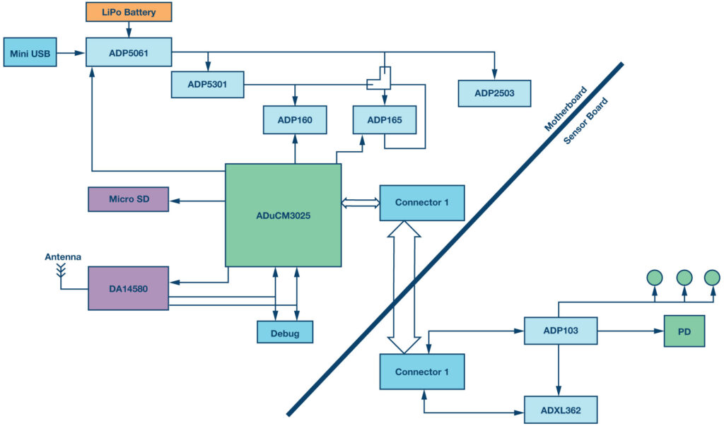
Inside this watch, we find a modular architecture consisting of a motherboard embedding the new Cortex-M3 microcontroller by ADI, which is the least consuming M3 controller on the market, named the ADuCM302x, and a 2.4 GHz radio transceiver allowing to send VSM data with the Google Thread protocol. On the daughter board is a photometric front end, the ADPD103, surrounded by three green LEDs and a photodiode, as well as the lowest power 3-axis accelerometer on the market, the ADXL362. These two devices are synchronized with one another to compensate for the movement of the person more efficiently.
The ADPD103 is a photometric front end, which works by reflective optical measurement to send an 8 mA to 250 mA current through its LED drivers to illuminate the external LEDs of the component. These LEDs illuminate the skin and use a reflected measurement through the photodiode, so the signal is acquired by the front end, then amplified, filtered, integrated, and converted by a 14-bit ADC, before being transmitted to a host via an I²C interface.
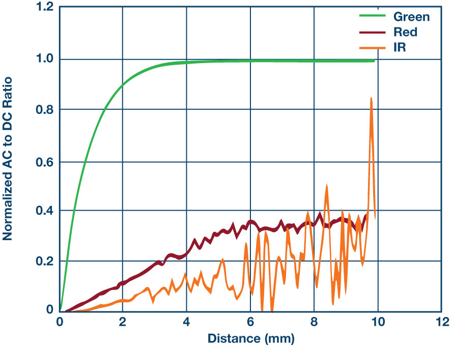
There are multiple advantages to having the LED and photodiode(s) externally: it allows for the selection of the number of LEDs, the color of the LEDs, their current strength, and especially for the optimal spacing of the LEDs with the photodiode to maximize the modulation index (it sets the ac-to-dc ratio, and thus the quality of the reflected signal). It also lets you choose the size of the photodiode (when the latter is wider, the modulation index will be higher) and possibly add to it an ultralow noise and low power current amplifier.
From the type of measurement performed (HRM—heart rate, pulsed oximetry) and the location of the measure on the skin comes choosing the color of the LEDs. For measurement of the heart rate on the wrist, we choose green LEDs, as their hemoglobin absorption is highest for the 500 nm to 600 nm wavelengths. When your heart beats the blood flow in your wrist and the absorption of green light is superior. Between beats, it decreases. By flashing green LEDs hundreds of times per second, the ADPD103 can calculate the number of times the heart beats every minute, which is your heart rate. It is recommended to space the green LED to the photodiode by 3 mm, or more conveniently, to increase the modulation index, as shown in Figure 3.
If we want to measure pulsed oximetry, then we choose a red LED and an infrared LED, and we will practice instead with the finger (we also benefit from an HRM with this method), because it has a strong capillary concentration. Pulse oximetry is a noninvasive method used by physicians to assess and quickly control the respiratory functions of a patient. The ratio of red and infrared light through the photodiode indicates the percentage of oxygenated hemoglobin vs. deoxygenated hemoglobin in your blood. The oxygen saturation in the blood is also called SpO2.
Oximetry is therefore based on the measurement of the light absorption of hemoglobin in blood capillaries and specifically on the rate of oxyhemoglobin (oxygenated hemoglobin) and deoxyhemoglobin (deoxygenated hemoglobin) of each red blood cell:
- A 98% SpO2 means that each red blood cell is loaded with 98% oxyhemoglobin and 2% deoxyhemoglobin
Analog Devices also offers module solutions (analog front end, photodiode, and LED in the same package) for surface constrained applications that do not require a lot of optimization of the optical measurement. Thus, the ADPD142, which includes a red LED and an IR LED, allows SpO2 measurement on the finger. Its successor, the ADPD144, offers an improved mechanical design that reduces internal light pollution (which is the direct light between the LED and the photodiode). It provides an average measurement error of 2.6% over 24,425 sample measurements, making it FDA compliant. The ADPD144’s package measures 5 mm × 2.8 mm, with a height of 1.35 mm.
As indicated above, to maximize the modulation index and, thus, the quality of the measured signal, there must be a minimum of spacing between LED and photodiode, which may not be optimal in a module where space is constrained. Thus, for applications such as sport watches with additional constraints due to the movement, perspiration, and the displacement of the skin-watch contact, Analog Devices recommends only solutions with external LED and photodiode from the photometric front end.
On the software offering side, Analog Devices provides drivers of the photometric sensors and accelerometers, and introduced at CES its own motion compensation algorithm, which runs on a Cortex-M3 core, the ADuCM3027, taking only 1.5 MIPS for 13 kB ROM, and 7.8 kB of RAM. This is a major breakthrough because until then, this type of algorithm required floating-point calculations, and thus, a Cortex-M4 processor type, which is more power hungry and more expensive. Note also that the color of skin or tattoos affects the quality of the measured reflected signal. It is recommended not to place the solution on a tattoo; the modulation index is slightly reduced for people with dark skin hence the need to optimize the optical design of the solution.
Ultra Low Power Platform
Now let us try to determine the power consumption of the watch discussed previously, assuming that we execute a motion compensation algorithm on the Cortex-M3 ADuCM3027 and some characteristics to establish the LED’s power consumption.
The ADPD103 sends a LED pulse train on one or two time slots. This allows, for example, a different number of pulses from one LED to another. The ADPD103’s consumption is the sum of the AFE and LED consumptions.
Let us take for example these conditions:
- FS = 100 Hz; 2 slots; pulse period A = 20 μs; pulse period B = 40 μs
- Number of pulses A = 4; number of pulses B = 8
- Maximum current in LED A = 25 mA;
maximum current in LED B = 100 mA - Pulse duration A = 3 μs; pulse duration B = 3 μs
- Thus the effective current in the LED_A =
(3 × 4/10000) × 25 mA = 30 μA - Thus the effective current in the LED_B =
(3 × 8/10000) × 100 mA = 240 μA - Current in the A channel of the AFE =
FS((20 + pulse count × pulse period) × Vddpeak + 0.13) =
100((20 + 4 × 20) × 0.0093 + 0.13) = 106 μA - Current in the B channel of the AFE =
FS((20 + pulse count × pulse period) × Vddpeak + 0.20) =
100((20 + 8 × 20) × 0.0093 + 0.20) = 187 μA - The total current of ADPD103 (including consumption of both LEDs) is 563 μA
As indicated above, the motion compensation algorithm developed by Analog Devices needs only 1.5 MIPS to operate, which we approximate to a running frequency 1.5 MHz. The power consumption of the ADuCM3027 being 38 μA/MHz, means the microcontroller consumes 57 μA. The ADXL362 uses 2 μA with a sampling frequency of 100 Hz, thus, the AFE and LED, Cortex-M3, and accelerometer system consumes 622 μA with this example. This low power consumption maximizes usage time without recharging the built-in LiPo battery in this watch. In standby mode, the ADPD103 consumes 3.5 μA. Its successor will decrease this value to 1 μA.
It should be noted that this example shows a power calculation that does not correspond to a precise application. You can get better or worse results depending on the targeted application, the current through the LEDs, and the sampling frequency having a direct link with the power consumption of the system. That said, ADI’s low power solutions help reduce the recharge period and power consumption of healthcare devices, which allows the elderly to live more independent lifestyles.


 combined with superior switching performance")


