


Abstract
This article demonstrates a reference design emulating the power architecture for a true wireless stereo (TWS) earbud application. It will show designers how they can improve the fast-charging speed of their application by nearly 4× while optimizing solution size and system BOM cost. Test results showing lower temperatures compared with a traditional solution are presented using thermistor and thermal imaging measurements. The design demonstrates numerous benefits offered by a solution with a single-inductor, multiple output (SIMO) architecture with autonomous headroom tracking.
Introduction
As the revolution in wearable devices continues, the demand for solid power architectures continues to increase. We’ve seen a large amount of growth of wearable health monitoring devices over the past decade, and the next generation of these devices is likely to include more features packed into the same tiny solution size. Typical requirements for wearable devices may include Wi-Fi, Bluetooth, and vital sign monitoring (VSM). The need for more features requires system-level and IC-level designers to get increasingly clever about their choices for powering wearable devices.
Power Challenges for Wireless Earbuds
A true wireless stereo earbud application currently requires several separate regulators fitting into a small solution size—after all, the entire system needs to fit in our pocket!
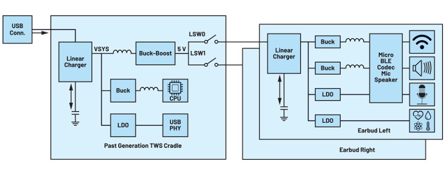
The typical power system for a TWS earbuds application is shown in Figure 1a. A DC-to-DC converter between the cradle and earbud is used to elevate the voltage to 5 V USB levels from VSYS. This provides enough headroom to keep the earbud’s linear charger out of dropout. However, a drawback of this solution is large efficiency loss due to the dropout voltage and losses across the linear charging FET on the earbuds. This is especially true when the earbud battery is at low state-of-charge. Charging at low efficiency increases thermal dissipation, which lowers the system battery life and product reliability.
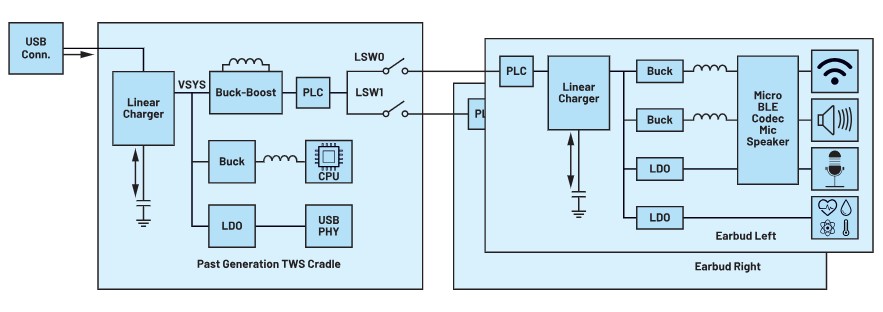
In some cases (Figure 1b), additional powerline communications (PLCs) are added to increase the efficiency of the system by tracking the linear charger’s headroom with the assistance of a buck-boost regulator on the cradle side.
However, the solution size for wearable products comes at a premium. The PLC chips and the inductors required by the buck outputs supplying the wearable device’s peripherals directly impact the size and the cost of the product for both of these traditional solutions.
A Better Solution: SIMO Architectures and Autonomous Headroom Tracking
SIMO power management ICs (PMICs) provide the architecture and efficiency required to satisfy compact design requirements. Battery-powered wearable applications also stand to benefit from a technology called autonomous headroom tracking, which minimizes the voltage dropped over the battery charging circuitry while providing optimal headroom to regulate the charge current. This reduces power loss and heat dissipation in the charging circuit without requiring additional components, which results in a wearable device that stays cool while charging and can even be allowed to charge faster.
The MAX77659 is a SIMO PMIC designed to improve efficiency and reduce the system board space and BOM size in wearable consumer and medical devices. This PMIC has three buck-boost outputs with efficiency up to 90% all utilizing the same inductor. It also includes an additional low dropout (LDO) regulator for sensitive applications requiring high power supply rejection ratio (PSRR), such as VSM. Furthermore, the SIMO architecture has intrinsic benefits in terms of efficiency, and it can provide ultralow quiescent current at minimal solution size.
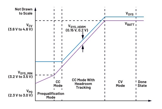
The MAX77659’s autonomous headroom tracking uses one of the SIMO outputs to minimize the voltage drop over the battery charging transistor while providing optimal headroom to regulate the charge current. The result is reduced power loss across the transistor and reduced heat dissipation, all without requiring additional components. A visualization of autonomous headroom tracking throughout the fast-charging process is provided in Figure 2.
MAX77659 Reference Design
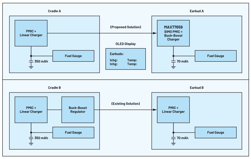
The reference design shown in Figure 3 compares the MAX77659 SIMO PMIC solution against a typical linear charging solution. Since the MAX77659 SIMO PMIC includes autonomous headroom tracking, the buck-boost regulator used in traditional solutions (Figure 3, Cradle B) can be omitted (Figure 3, Cradle A). This improves the overall system battery life by increasing charging efficiency while reducing solution size and BOM cost.
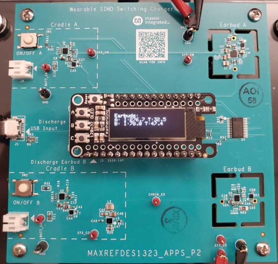
Figure 4 shows the full PCB for the MAX77659 reference design. The design includes two pairs of cradle/earbud solutions—one utilizes the MAX77659 SIMO PMIC design (Cradle/Earbud A), while the other follows the typical linear charger design (Cradle/Earbud B), using a MAX77734 linear charger. Push-buttons on the base board toggle charging for both the A and B branches, and an OLED display shows the charge current and temperature measured from the earbud’s MAX17260 fuel gauges. The screen also displays the charger status, which shows when the charger must reduce charge current because of overheating.
Battery Management System Charging Standards
The Japan Electronics and Information Technology Industries Association (JEITA) publishes standards related to battery management systems that provide rigorous and robust methods to promote system safety and reliability for the end user by reducing system and battery wear. It is common for end applications to utilize integrated JEITA protection features that reduce charge current and voltage levels during the constant current (CC) and constant voltage (CV) phases of battery charging. If the system gets too warm, the regulated charge current and voltage may be reduced to allow the circuit to cool. This throttling of current protects the end user from discomfort and preserves the system’s reliability and lifetime. Unfortunately, throttling the charge current also means a slower charge cycle. The need to incorporate JEITA features represents a design trade-off that creates pressure on wearable designs. This pressure can be alleviated by a solution that can maintain better thermal performance during long exposure to high charge currents.
Performance Comparisons
To examine the thermal performance of both the traditional and proposed solutions, a 1-minute charge test was run at 270 mA CHG_CC (normal CC current) and 75 mA JEITA_CC (CC current above a JEITA_WARM temperature threshold). The goal was to show the thermal differences over this period and examine whether higher charging speed could be maintained for the two solutions without triggering JEITA protection. A battery simulator was used for the benefit of repeatability and isolating the thermal rise to that experienced by the IC alone. The thermal threshold used for this test was 45°C, a 21°C rise over the ambient temperature. The PCB for the reference design is a 6-layer board with copper thicknesses of 0.0014 inches, 0.0007 inches, 0.0007 inches, 0.0007 inches, 0.0007 inches, and 0.0014 inches. The conditions of the test are presented in Table 1, and the results are presented in Table 2.
| Test Configuration | |
| CC | 270 mA |
| JEITA CC | 75 mA |
| JEITA Warm | 45˚C |
| Batt Voltage | 3.0 V |
| Solution A (MAX77659 SIMO PMIC) | Solution B (Linear Charger) | |||||
| Time (s) | Status | Temp (˚C) | Charge Current (mA) | Status | Temp (˚C) | Charge Current (mA) |
| 0 | Off | 24.3 | 270 | Off | 24.0 | 270 |
| 15 | CC | 29.1 | 270 | CC | 43.0 | 270 |
| 30 | CC | 32.2 | 270 | JEITA CC | 47.1 | 75 |
| 45 | CC | 33.3 | 270 | JEITA CC | 47.3 | 75 |
| 60 | CC | 35.4 | 270 | JEITA CC | 44.2 | 75 |
Over the course of this test, the MAX77659 SIMO solution rose by 11.1°C within 1 minute, and its rate of temperature increase slowed significantly after the first 30 seconds. The proposed solution did not enter JEITA mode at any point during the test. With the typical linear charging solution, the part rose by almost 20°C within just 15 seconds, and it triggered JEITA protection—throttling charge current within just 30 seconds.
Thermal Imaging Results
Furthermore, to examine the thermal behavior without JEITA protection enabled, a thermal camera was used in a separate test to measure the temperature of both the SIMO PMIC solution and the linear charger solution. The parameters were the same as in the first test, and only JEITA protection was disabled.
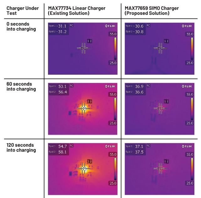
The temperature of the linear solution rose to 58.1°C over the course of this 2-minute test, while the SIMO PMIC only rose to 37.5°C. Based on these results, the SIMO solution was able to reduce the temperature rise from the linear charging solution by about 72%.
Conclusion
This article benchmarks the MAX77659 SIMO PMIC against traditional linear charging solutions in an emulated TWS earbud application, showing the benefits of autonomous headroom tracking with a switching charger solution. The results presented show massive thermal improvements—a heat reduction of 72% allowed the SIMO PMIC solution to safely maintain almost 4× the charge current of a traditional linear charging solution. This helps the system charge lightning fast while staying cool and comfortable, addressing key pain points for wearable devices.
The MAX77659 SIMO PMIC enables safe, reliable, and comfortable charging solutions for the next generation of wearable devices while also improving efficiency and reducing the necessary solution size and system BOM count. For more information, check out Analog Devices’ broad platform of SIMO PMICs and fuel gauges to see the best-in-class low power solutions for your next-generation wearable devices.


 combined with superior switching performance")


