


Abstract
This article explains the correct system-level testing approach to evaluate the controller area network (CAN) transceiver. It explains why this approach is superior by showcasing how actual data transfer problems can be avoided while performing data transmission from one CAN node to another in a multi-CAN node system. After reading this article, the reader will have a better understanding of the CAN system and will be able to select the correct CAN transceiver for the specific multinode CAN system.
Introduction
The CAN is a robust communication standard, which is used to allow different sensors, machines, or controllers to communicate with one another. The CAN interface is popularly used in industrial automation, home automation, and automobiles as it is more robust and handles the bus contention effectively.
Legacy CAN2.0 offers 8-byte payload and supports data rates up to 2 Mbps. Sometimes, a 2 Mbps data rate is not sufficient for critical communication events and thus CAN. org has come up with a new communication protocol, CAN-FD, allowing high data rate communication up to 10 Mbps.
The CAN-FD Flexible Data Rate
The primary difference between the legacy CAN and CAN-FD is the flexible data (FD). In CAN-FD, the data rate (that is, the number of bits transmitted per second) is increased to 5× faster than the classic CAN (10 Mbps for the data payload only; the arbitration bit rate is still limited to 1 Mbps for compatibility). The message payload size in CAN-FD is increased to 64 bytes from the legacy CAN size of 8 bytes.
Using CAN-FD, sensors can change data rates with larger or smaller payload. Faster data speed and larger payload capacity result in many system-level operating advantages compared to the legacy CAN in a modern factory.
CAN Communication—The Basics
The CAN communication consists of two main components: (a) the CAN controller and (b) the CAN transceiver as shown in Figure 1.
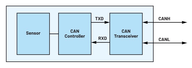
The CAN controller handles the data link layer of CAN communication, whereas the CAN transceiver handles the physical layer. Let’s take a brief look at the CAN transceiver physical later.
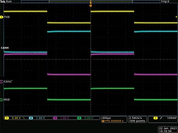
In CAN protocol, Logic 0 is called the dominant bit and Logic 1 is called the recessive bit. As CAN is a differential protocol, the voltage difference between CANH and CANL determines the logic levels of transmitted and received signals. If the CANH-CANL voltage is greater than 1.5 V, a CAN receiver identifies that bit as Logic 0. Whereas, if the CANH-CANL voltage is less than 200 mV, a CAN receiver identifies that bit as Logic 1. Figure 2 shows the continuous transmission of digital Logic 1 and Logic 0 bits on the TXD pin of the CAN transceiver and its equivalent CAN bus levels on CANH and CANL pins. Based on the difference between CANH and CANL voltages, the receiver loops back signals on the RXD pin.
Let’s look at the CAN data link layer now, which formulates the data frame for the controlled transmission of this bit stream. It also helps in error detection and bus contention resolution. Figure 3 shows a standard CAN frame format.
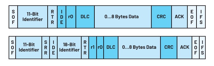
Every node starts the data frame with start of frame (SOF), which is the first dominant bit. The 11-bit identifier is each node’s unique address. IDE indicates the frame format. Logic 0 in this bitfield indicates the standard CAN format, whereas Logic 1 in this bitfield indicates the extended CAN format. r0 is a reserved bit. The DLC field indicates the number of data bytes to be transferred. In the standard CAN2.0 frame, up to 8 bytes can be transferred. The receiving node acknowledges this data frame by sending the dominant bit on the bus. Finally, end of frame (EOF) is one recessive bit, which marks the end of one data frame.
Most of the time, while choosing CAN transceivers, customers evaluate the CAN transceiver by sending a bit stream on the TXD pin of the CAN transceiver through the function generator. Although this method is perfectly suitable for the evaluation of a single-node CAN, it seems to be flawed while developing a multinode, far-spaced CAN system. Hence, the new CAN controller and transceiver testing is necessary to select the right CAN transceiver for your system. What are the reasons behind this methodology?
The Arbitration Methodology
The primary reason for this system-level testing approach is the arbitration feature of the CAN protocol. If two nodes try to occupy the bus simultaneously, access is implemented with a nondestructive, bit-wise arbitration. The node that sends a first identifier bit as a zero (dominant), while the other nodes send a one (recessive), retains control of the CAN bus which goes on to complete its message. Figure 4 shows the arbitration scheme between two nodes.
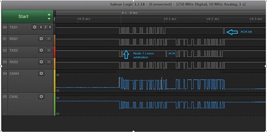
In this figure, Node 1 and Node 2 are connected to each other over the CAN bus. So, CANH and CANL signals are common to both nodes. TXD1 and RXD1 are signals for Node 1, whereas TXD2 and RXD2 are signals for Node 2. As you can see, the f irst three bits of Node 1 and Node 2 are the same: 1, 0, and 1, respectively. The fourth bit of Node 2 is 1, whereas Node 1 is 0. As Node 1 has a dominant bit, it wins the arbitration and continues sending the complete message. The message is acknowledged by Node 2. Once Node 1 finishes the transmission, Node 2 starts the sending of the message. Node 1 acknowledges this message.
Each node has a unique identifier ID. Thus, this 11-bit identifier ID is used in the arbitration process. These bits will be read back by the controller to identify the priority of the message transmission. In CAN-FD, the arbitration bit rate can be kept the same or different from the data bit rate. In CAN2.0, both the arbitration and data bit rate are the same.
In legacy CAN2.0 systems, sometimes the bit rate is increased from the standard CAN2.0 recommended 1 Mbps to allow faster data transmission. In CAN-FD systems, the arbitration bit rate is limited to a 1 Mbps data rate and the data bit rate can be up to 10 Mbps. During the arbitration phase, which includes the 11-bit identifier and SOF bit, every transmitted bit is read back for synchronization.
CAN nodes synchronize on observed edges on the CAN bus, but the signal propagation time on the bus line introduces phase shifts between the nodes. CAN’s nondestructive arbitration mechanism for media access control requires that the phase shift between any two nodes is less than half of one bit time. This lower boundary for the nominal bit time defines an upper boundary for the nominal bit rate as well as for the bus length. Thus, the rise time and fall time of the RXD, the loop delay of the CAN transceiver as well as the cable come into the picture. At a higher bit rate, for example, 10 Mbps, the propagation delay, and rise time/fall time need to be less than 50 ns.
Thus, the arbitration bit rate in CAN-FD is limited to 1 Mbps, allowing higher margins for the synchronization of many possible nodes. However, CAN-FD is new and is not yet implemented in all CAN systems. In some cases, the CAN-FD controller is not available or it is considered a costly addition to the system, and thus customers proceed with standard CAN controllers. In these systems, CAN nodes need to communicate at higher bit rates (>2 Mbps) due to critical sensor information and possibly shorter cable length between the nodes. In such cases, rise time/fall time symmetry and the propagation delay of the transceiver may limit the upper boundary for allowable data communication.
System-Level Testing Is Required for CAN Transceivers
Let’s take an example of the CAN transceiver MAX33012E, which has been tested up to 13.3 Mbps with a 20 m cable. As you can see, in Figure 5, the TXD2 bit width is 75 ns (corresponding to 13.3 Mbps) and the RXD2 bit width is 72 ns. As the controller samples at 80% of the TXD bit width, the minimum RXD bit width including rise time/fall time and loop delay of the RXD required is 60 ns. In Figure 5, you can see that the received bit width is 72 ns. Thus, the MAX33012E satisfies the condition and is robust enough to work at higher bit rates. In this situation, the CAN controller doesn’t detect any error and continues to perform data communication.
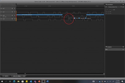
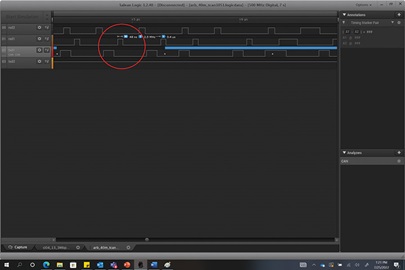
Figure 6 shows a scope shot of a competitor part, which was also tested at 13.3 Mbps. With this part, the transmitted bit width was 75 ns (corresponding to 13.3 Mbps) and the received bit width was less than 80% of the transmitted bit width (48 ns). Thus, the arbitration phase bit transmission failed, leading to an error in communication, and finally the system stopped working.
These kinds of data transmission errors can only be uncovered by performing complete system-level testing, which includes multiple CAN controllers, CAN transceivers, and a long cable.
Conclusion
System-level testing of the CAN transceiver helps to unveil the possible future data transmission problems in your system. These problems can be avoided by evaluating a CAN transceiver with a CAN controller and a cable that satisfy the required timing and voltage specifications. Robustness of the CAN system is a cumulative performance of each component in the CAN system. Evaluating only one component, or CAN transceiver, does not provide an accurate measure of system functionality. Performing a prior validation of the system is much more cost-effective than replacing a faulty one. Thus, we highly recommend system-level testing before choosing your CAN controller.


 combined with superior switching performance")


