


Abstract
This article describes some of the unique challenges of designing wearable devices and how to optimize power efficiency to reduce size. It covers the importance of the operating voltage and how to select the right voltage regulators. It also explains the importance of battery fuel gauging and ends with a summary describing an example of a highly integrated device optimized for these ultra-portable/wearable applications.
Introduction
As people turn to electronics for entertainment, physical activity can decline and lead to health issues. While technology may be one of the causes of obesity, technology can also be used to fight the problem. Today there are electronic pedometers and fitness trackers that encourage more physical activity by reporting activity levels, and there is data to demonstrate the effectiveness of this approach.
The number of options for “wearable” fitness trackers continues to grow, and they continue to add features beyond simple step counting to help promote physical activity. For any of these devices to be effective, however, they need to be used. And for people to use them, they need to be unobtrusive and low maintenance; to be so small and so light that you forget they are there; and to provide a long time per charge to minimize the hassle of recharging. The energy available from the battery is tied to the size of the battery, so it can be difficult to extend the time between charges without making the device larger and heavier. Because the battery is typically one of the largest components in a wearable device, a delicate balance between power budget and size is required in the design.
This article will discuss how to reduce the size and weight of wearable devices without compromising performance. Achieving these goals can increase the utilization of these devices and make a positive difference to the overall wellness of the community.
The Design Challenge
To reduce the size and weight of these wearables, the energy consumed from the battery needs to be minimized so smaller batteries can be used. In some ways wearables are like any other battery-powered application, but the scale is so much smaller that a different level of optimization is required.
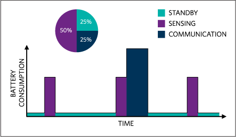
A wearable device must quickly manage the higher power-consuming tasks and spend as much time as possible in an idle standby state (Figure 1). But the current available here is significantly smaller than a typical mobile application. To get a week of run time from a 50mAhr battery, the average current needs to be less than 300µA. Allocating 25% of the power budget to standby is less than 75µA. A buck regulator with a quiescent current (IQ) of 30µA would consume almost half of this budget, thus making a low-IQ linear regulator seem like a better option. While standby consumes tens of microamps, there are often high-peak-current peripherals in the system such as displays or radios that may need tens of milliamps. Without the efficiency of a buck regulator it will be difficult to meet the communication power budget. Consequently, optimizing power across the large dynamic range of loads requires balancing trade-offs and careful attention to the detailed power specifications.
Reduce the Voltage
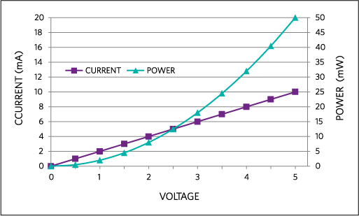
Whether in an active or standby state, the components in a wearable device need power to operate. To reduce the load to the battery, we must minimize power consumption. Keep in mind that power is the product of the voltage times the current, and that current is typically proportional to voltage. So the power is often related to voltage squared. The dramatic difference between current and power is easily visible when the current and power consumption of a resistor are plotted versus the voltage applied, as in Figure 2.
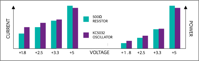
While active devices are not purely resistive loads, the current required for charging and discharging capacitors is also dependent on the voltage applied. The power for many active devices will vary as a function of the square of the voltage applied. An example of this can be seen by comparing the current and power consumption of a simple active device like the KC5032 oscillator to the current and power consumption of a resistor (Figure 3). This voltage-squared relationship partially explains why computing power per watt advances so rapidly with modest reductions in voltage. It also explains why adding a linear regulator can reduce power consumption, even though the conversion is inefficient and input current is basically equal to the output current.
Many devices regulate the voltage internally for power savings and other reasons. The internal regulation is most commonly linear, so it will minimize the current variation. Nonetheless, the overall power consumption is still linearly related to the input voltage. In general, to minimize power consumption for most functions in the system, it usually helps to select from the lowest voltage components available and to operate them at the low end of their input voltage range.
Choose the Right Regulator
While it is important to select the right operating voltage, it is equally important to select the right regulator to generate that voltage. As mentioned previously, a linear regulator inside a device can reduce power consumption by allowing the internal circuitry to draw less current. Linear regulation, however, does not take full advantage of the voltage reduction. The power is reduced because the current through the regulator is reduced, but the power consumed is still the input voltage times the current. The power needed is only the output voltage times the current; the rest of the power (current times the difference between input and output voltage) is consumed by the linear regulation.
A switching regulator is needed to take full advantage of the reduced voltage. A common switching regulator can easily consume the entire standby power budget. Because these devices spend such a high percentage of their time in standby, it used to be necessary to sacrifice active efficiency and use a low-IQ linear regulator. Fortunately, today there are buck regulators with sub-1µA IQ that make the active-versus-standby efficiency trade-off unnecessary.
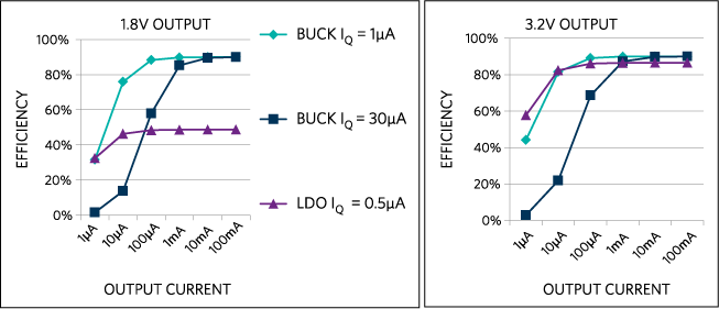
The battery current reduction of moving to one of these low-IQ regulators can be quite dramatic. If the component can run from 1.8V and the source is a rechargeable Lithium polymer battery with an average voltage of 3.7V, then the battery current can be cut nearly in half. But a buck regulator is not always the optimal solution, particularly if the output voltage is > 80% of the input voltage. A buck regulator is often about 90% efficient. When regulating from 3.7V down to 3.2V, even a linear regulator will be 85% efficient, but the linear regulator does not require an inductor. Plotting the efficiency-versus-output current as in Figure 4, the 1µA buck regulator has clear advantages when regulating to 1.8V for loads less than 1mA. But note that there is little difference when regulating to 3.2V. Since these devices spend so much time in standby, the 1µA buck regulator is the best choice for a 1.8V output. Nonetheless, the reduced board space of the linear regulator makes it a better choice for a 3.2V output. Just remember that all switching converters are not created equal. Carefully review the converters’ behavior under your specific operating conditions.
While many microcontrollers contain integrated regulators, the internal regulators are not always the best choice for lowest power consumption. It is just as important to review the details of internal regulators as it is to review external regulators. As core voltages drop below 1.8V, moving from a linear to a switching regulator can cut the core power consumption by more than half. This is precisely why many microcontrollers provide the ability to disable the internal regulator. It is not safe to assume that the included regulator is optimal, and there can be a significant power penalty for yielding to the temptation of simply using whatever the microcontroller provides for core regulation.
Know Your Battery
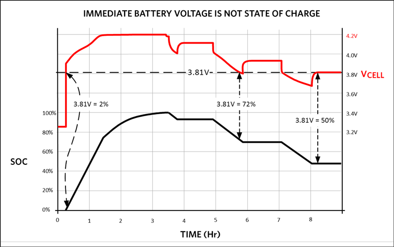
One of the worst user experiences is when a device stops unexpectedly. A runner with a pedometer laments, “But the battery bars still look good?” No one expects the device to shut down when the battery indicator states that there is still charge available. So it is critical that the indicator be accurate. Any uncertainty in the battery state of charge (SOC) status must be subtracted from the available charge reported to the user. To guarantee a minimum time between charges, the battery must be “oversized” to allow for the inaccuracy of the measurement.
Given the significance of the battery in the system design, how you choose to measure the status of the battery will directly affect the size, cost, and overall user experience. With the tiny currents common in wearable devices, coulomb counting is simply not practical. The sense voltages are so small that micropower amplifiers are not adequate and the frequency of measurements required consumes far too much power. A voltage monitoring technique is the only feasible solution.
Rechargeable Lithium batteries can be very difficult to monitor by voltage alone. Simply reading the battery voltage with an ADC does not tell you the SOC of the battery (see Figure 5), but fortunately there are fuel gauges specifically designed to meet the requirements of these applications. Maxim Integrated’s proprietary. The ModelGauge algorithm provides the best accuracy for reporting battery capacity. Most would agree that an accurate battery SOC measurement could be priceless when you are trying to maintain a thin profile or extend time between charges.
Bringing It All Together
The challenges of designing tiny wearable devices require different optimizations than the typical mobile application. Components and specifications that were considered unimportant noise before are now critical factors for meeting performance requirements. Not only does each function need to be optimized for the new power constraints, but they must all be implemented in the smallest space possible. There is little room in these devices for glue logic or even passive components, so integration is critical.
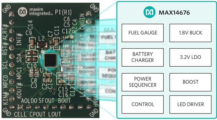
Fortunately, there are integrated devices optimized for these wearable applications. Single-chip wearable, charge-management solutions are available combining power regulation, battery management, and supervisory functions in tiny WLP packages like the one shown in Figure 6. To enable lower voltages with optimal regulation, this device includes both a 1.8V buck regulator with less than 1µA IQ and a low-IQ 3.2V LDO. For accurate battery monitoring it utilizes the ModelGauge technology. It also integrates other features commonly found in these wearable applications: display/backlight power, supervisory functions like power on/off, and sequencing control. Products like a wearable charge-management solution are helping companies better utilize the battery and strip the weight out of their fitness trackers. Now they can provide optimally powered, smaller, lighter, and less obtrusive wearable devices that people might actually use.


 combined with superior switching performance")


